3
\$\begingroup\$

I need to measure 300VAC. I am using the following circuit and it is working good. In the circuit, I am using 2mA/2mA current transformer. More details about this transformer are available here. Measuring a 300VAC, 60Hz using 2 power modules
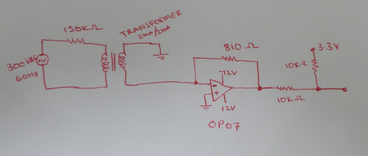
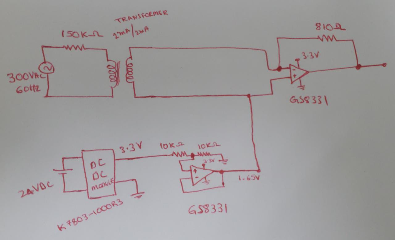
However, I want to use only one power source of 3.3V to reduce my PCB size and cost. Is the following circuit good? If it is not a workable solution, pelase suggest me what would be the better solution.

Measuring 300VAC, 60Hz using only one supply voltage

EDIT:

The transformer is a current transformer with 1:1 relation of 2mA/2mA. Also, there is a limit of secondary resistance. The secondary resistance should be less than 100 ohms. It is not a problem to short circuit the secondary. More details are available at the following link.

https://www.micro-transformer.com/2ma-2ma-voltage-transformer-ZMPT101C.html

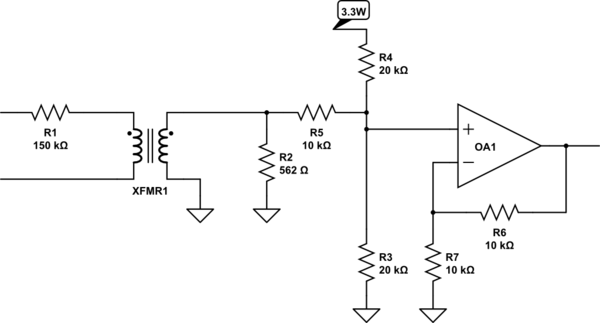
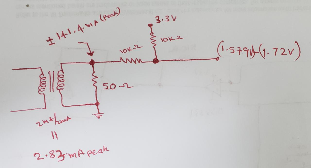
If I use a voltage divider (solution suggested by Kuba hasn't forgotten Monica) as shown in the following circuit, the voltage swing at the output is little and hence, I cannot use the complete range of a microcontroller. So, I suppose the use of an operational amplifier is required.

A solution with voltage divider

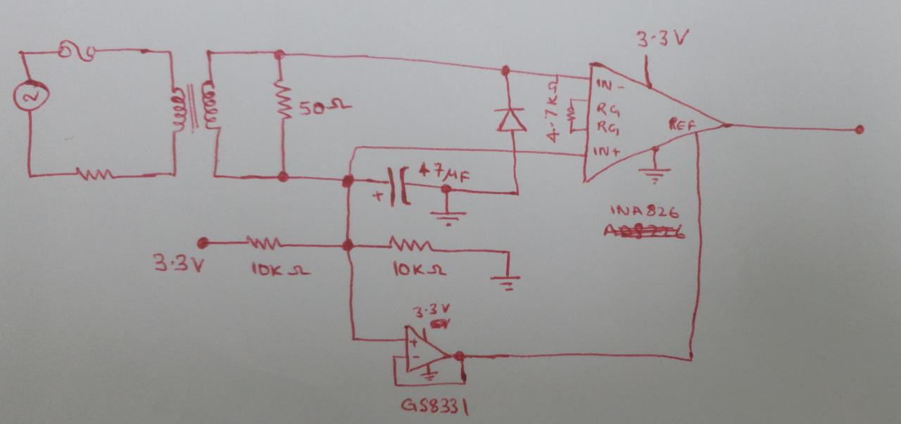
Edit 2: Thanks to Kuba hasn't forgotten Monica, I understood several other mistakes in my previous circuits. Upon including Kuba's suggestions, I have the following circuit suggestion. Is it good to use a instrumentation amplifier to take full advantage of the microprocessor's ADC?

Circuit with instrument amplifier

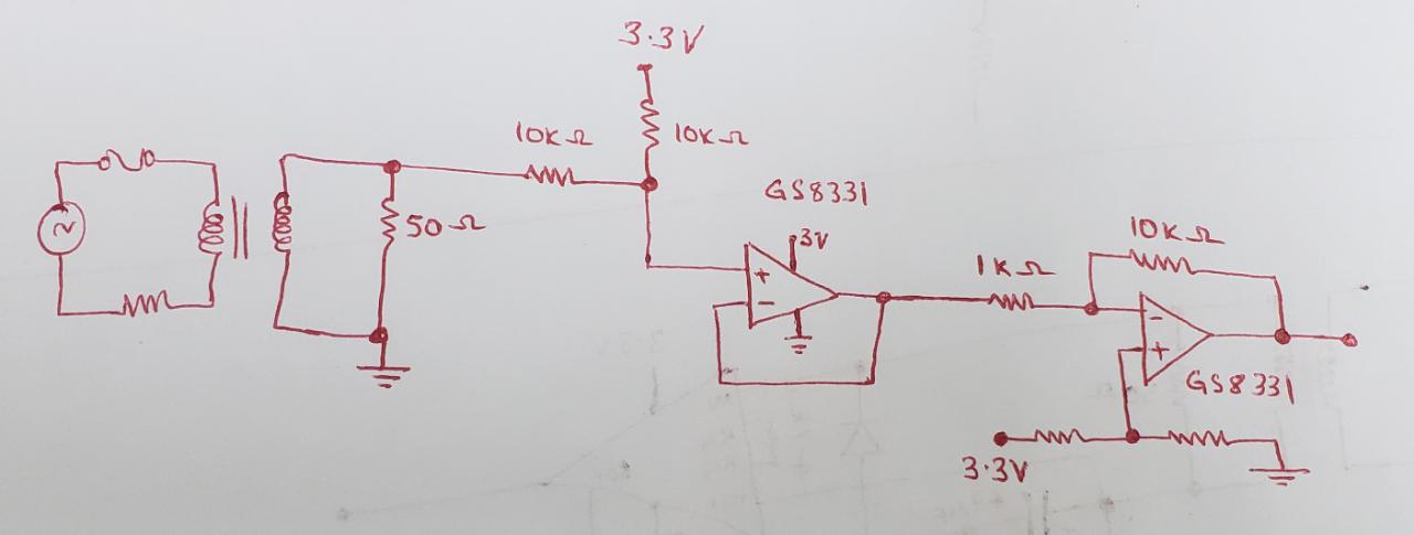
Edit 3: I came up with another circuit which seems to work fine. Please give a look at it.

Circuit with two op-amps

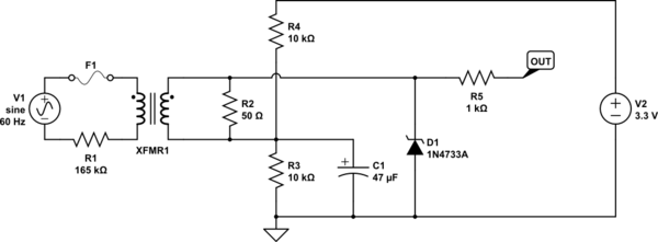
Edit 4: Solution:

Finally I am able to solve it. The following circuit is working good.
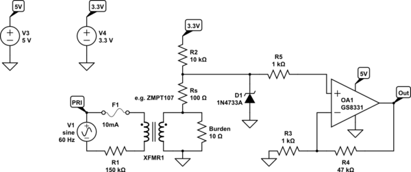
schematic

simulate this circuit – Schematic created using CircuitLab

\$\endgroup\$
9
  • 1
    \$\begingroup\$ Where is the 300VAC coming from? There is no input protection so this would be a problem when measuring mains voltages. \$\endgroup\$
    – Kartman
    Commented Apr 19, 2022 at 15:01
  • \$\begingroup\$ @Kartman, around 255AC is the nominal voltage between lines. However, I am using a 300V to make sure even a slight increase in voltage could be measured. Also, I haven't worked on the protection part yet. Now I am working on the measuring part. Do you think varistor is sufficient as protection? \$\endgroup\$
    – SKGadi
    Commented Apr 19, 2022 at 15:04
  • 1
    \$\begingroup\$ If you want to measure mains, use a mains metering ic. It does all the hard work for you. \$\endgroup\$
    – Kartman
    Commented Apr 19, 2022 at 15:08
  • 1
    \$\begingroup\$ What is the transformer ratio? Also, in words, what are you trying to do with the stepped down voltage? As for safety, you need 2 types, overcurrent and overvoltage. \$\endgroup\$ Commented Apr 19, 2022 at 15:16
  • 1
    \$\begingroup\$ @SKGadi See updates to my anwser. \$\endgroup\$ Commented Apr 19, 2022 at 18:44

2 Answers 2

3
\$\begingroup\$

Re. Circuit #1

The op-amp is incorrectly biased.

Re. Circuit #2

  1. Add a fuse! Assume that the rest of the circuit can fail shorted.

  2. Accommodate the +10% high line condition by increasing the V-I resistor R1 to 165k ohm.

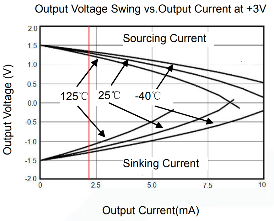
  3. The gain is too high and the op-amp's output attempts to swing close to the rails. Recall that the full transformer output current flows into the op-amp output. After all, that's the only destination it can flow into! The op-amp won't be able to drive close to the rails at such a current. According to the datasheet, with a 2mA load the output can swing to about +/-0.4V away from the rails, i.e. between 0.35V and 2.95V:

    The output voltage swing vs load current

    The gain has to be decreased to lower the output voltage swing, i.e. the feedback resistor value has to be increased.

  4. Add transient protection to the transformer secondary. Disconnecting the input will create an inductive kick that will overstress any load, be it an op-amp or an MCU.

Re. Circuit 3

The transformer is used as a current transformer, so the output current is exactly the input current. With a 150k V-I resistor at the input, the output current will be exactly 2mA across the recommended 50 ohm load. That's only 100mV RMS. The "+/-141mA peak" annotation is incorrect: the secondary current is 2mA RMS, maximum.

The voltage divider as shown further divides this small signal by half. At the very least, you'd want to move the divider to bias the winding, so that no amplitude would be lost:

schematic

simulate this circuit – Schematic created using CircuitLab
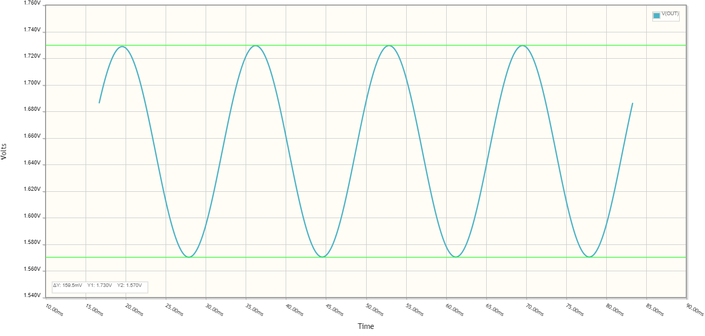
The output looks as follows:

The output waveform of circuit #3 with a 50 ohm load

Discrete Current Source I-V Converter

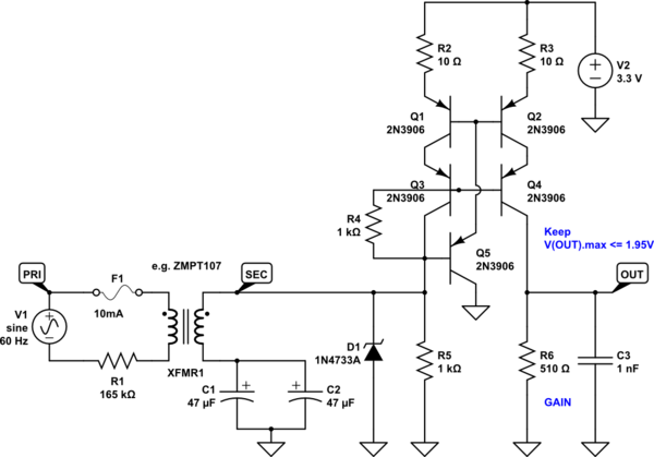
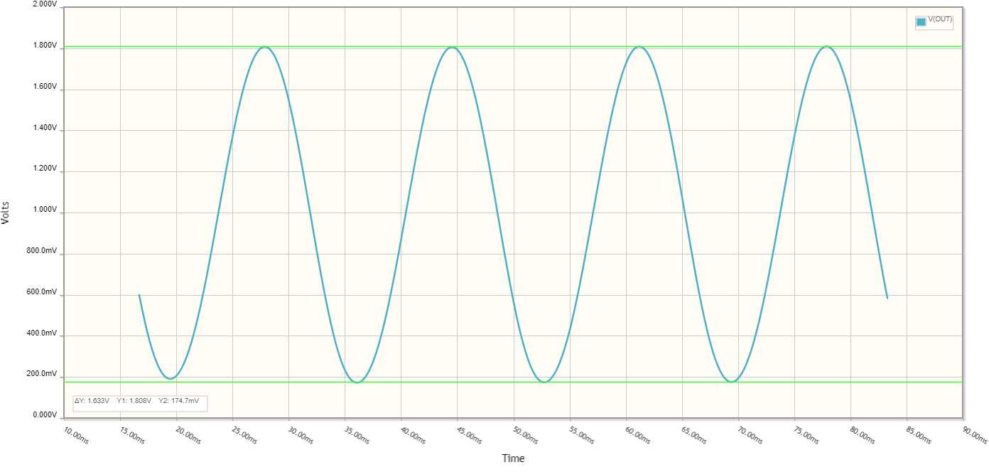
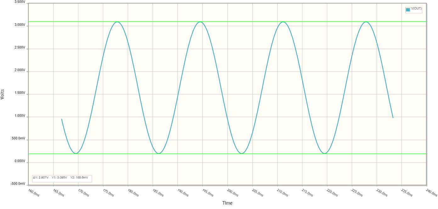
If you can accommodate a slightly smaller output voltage range than the full 0 to 3.3V, then a current mirror would be another cheap solution for an I-V converter. The circuit below presents <100 Ohm load impedance to the transformer secondary. The output voltage at nominal line is 1.8Vpp.

schematic

simulate this circuit

The output is shown below.

The output waveform of the discrete I-V converter

At volume, this probably costs <$0.25.

Cheap Op-Amp I-V Converter

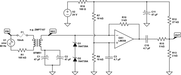
As for an op-amp: The good old LM358 and LM324 work with input and output down to ground, and will do the job straight from 24V supply, and is cheap. LM324 and LM358 have stock levels in millions.

schematic

simulate this circuit

For filtering the supply to the op-amp, it’s OK to use a simple RC filter.

The op-amp drives about 10Vpp through the 3k feedback resistor: that's 2mA RMS into the transformer secondary.

The output is then scaled down to fit into the 0.2-3.1V output range at nominal line voltage.

The op-amp can be any jellybean part not worse than LM358, ie. TL071, TL081, LM324, etc. With LM358 as shown, you have a second op-amp you could do something with.

The output waveform of the op-amp I-V converter

The output impedance of this circuit is about 1.35k ohm. The fault condition output current into the MCU pin would be 3mA peak if the output of the op-amp suddenly saturates at 20V. This fault current has a transient character, since the coupling is capacitive. So the op-amp failing with output shorted to either rail will not damage the MCU.

\$\endgroup\$
9
  • \$\begingroup\$ The circuit shown in the Cheap Op-Amp I-V Converter is the best and simplest, however, I see one problem. Again, it is because of my application specific problem. The 24VDC comes from a battery and its voltage may change with time. Since 24 is taken as reference, my output may change. Is it possible to use 3.3V source as reference to the positive pin? Also, are you considering that the op-amp LM358 is not rail-to-rail, so it may not reach zero? \$\endgroup\$
    – SKGadi
    Commented Apr 19, 2022 at 19:17
  • 1
    \$\begingroup\$ @SKGadi LM358 in this application is swinging from about 6 to 16V, far from rail to rail. The output resistor network rescales it to 0-3.3V. The impedance to transformer secondary is virtual: a higher impedance is transformed into a lower one. You see that by looking at the current waveform coming out of the transformer. It’s close to zero ohms for LM358, and about 80 ohms for the discrete circuit. Ideal load for those transformers is 0 ohms, because they already have 150 ohms built-in resistance of the winding itself 50 ohms just adds to it. \$\endgroup\$ Commented Apr 20, 2022 at 20:59
  • 1
    \$\begingroup\$ LM358 and LM324 have input that goes past ground by 0.1-0.2V, and output that swings as close to zero as you want it with a pull-down. These circuits are can be simulated with a click. Please look at the waveforms, it literally takes a minute or less. You can easily virtually probe them in the simulator. That’s why I took time to ensure the simulations worked :) Your final solution will be destroyed by common spikes, you pretty much shorted the winding to op-amp input. Only low trace impedances will protect the op-amp, so design those for 1GHz bandwidth ESD spikes. \$\endgroup\$ Commented Apr 20, 2022 at 21:05
  • 1
    \$\begingroup\$ You don’t care about the offset much: the software takes a running average over 1 line cycle. The exact offset is not relevant as long as the signal remains unclipped. You can always lower the gain a bit. BTW, you’ll get a resolution way better than 8 bits in this measurement done right. You have to fit a sine wave to the data, and you’ll easily get 10 bits of amplitude resolution even with very simple code. If anything, some noise added to the signal would reduce nonlinearities of the ADC. Line inputs are usually plenty good at that already :) \$\endgroup\$ Commented Apr 20, 2022 at 21:09
  • 1
    \$\begingroup\$ Averaged over 10 seconds you can probably eke out 12 bits of amplitude in this application without trying too hard, and 16 bits of you use state of the art methods – when sampling is phase locked to line frequency. The phase lock can be closed in software, and you only need a digitally controlled oscillator chip to act as a sample clock for the ADC. Some MCUs offer that on-chip. \$\endgroup\$ Commented Apr 20, 2022 at 21:12
3
\$\begingroup\$

Absent the question of proper circuit protection, that should work except that you seem to be designing for 300V peak. 300VAC generally means 300V RMS; that, in turn, means about 425V peak -- your circuit, as drawn, will saturate.

When it does saturate, the op-amp will no longer be actively controlling the voltage at it's \$V_-\$ input -- you'll be forking that job onto the op-amp's protection diodes, or otherwise whatever circuitry happens to be there.

Moreover, while the thing is advertised to have a 20mA output, it doesn't specify how well it works at that much output current.

If I were to use the same front-end (\$150 \mathrm k \Omega\$ resistor and that current transformer), I would terminate the current transformer with a passive resistor to ground. Then I would use the op-amp as a plain old voltage buffer, probably with higher resistances so the output is only loaded with \$10\mathrm k \Omega\$.

I haven't actually checked this circuit, and the coffee hasn't kicked in yet this morning -- feel free to analyze, simulate, and otherwise check it carefully before use. It should give you a sine wave riding on 1.65V, scaled so that it stays within the rails when you've got a 300V RMS sinewave on the input.

schematic

simulate this circuit – Schematic created using CircuitLab
\$\endgroup\$
2
  • \$\begingroup\$ Hi, I missed mentioning one important detail. The resistance connected to the secondary has a limit. I updated it in the question. In this case it is 100 ohms. So, I don't want to move above 50 ohms to be safe. \$\endgroup\$
    – SKGadi
    Commented Apr 19, 2022 at 16:40
  • \$\begingroup\$ You saved my life finding out that I made mistake considering RMS in the calculation of resistance. I will update that part. \$\endgroup\$
    – SKGadi
    Commented Apr 19, 2022 at 16:40

Your Answer

By clicking “Post Your Answer”, you agree to our terms of service and acknowledge you have read our privacy policy.

Not the answer you're looking for? Browse other questions tagged or ask your own question.