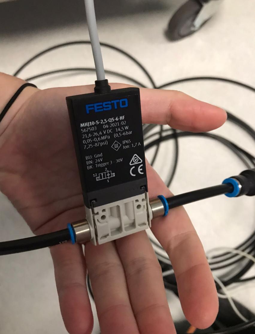
I'm currently working on a project for university, where I want to control a Festo solenoid valve (MHJ10, https://www.festo.com/cat/en-us_us/data/doc_enus/PDF/US/MHJ_ENUS.PDF) via a Raspberry Pi GPIO. The valve runs equipped with 3 cables, "GND", "24V+" and "Trigger". According to the Data Sheet, the Trigger works with any voltage between 3-30V. But how this trigger has to be connected in the circuit is not mentioned in the data sheet and my colleagues and I tried different set-ups, but nothing works as it should so we are a bit lost now tbh. Maybe someone of you knows the answer!
in all Set-Ups, the valve is connected to pressured air with pressure about 1 bar
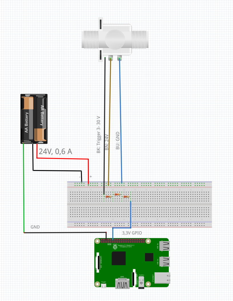
Set-Up 1:
- The 33kOhm resistors in serie are there to reduce the current to 0,0001 A (required according to the data sheet)
- we connected the trigger to the GPIO 18 of the raspberry pi and let the GPIO go to high (3,3V) and to low several times in a row. We checked whether the voltage is really changing between GPIO 18 and GND with a multimeter and yes, it was.
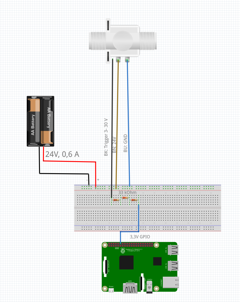 Outcome:
valve did not open
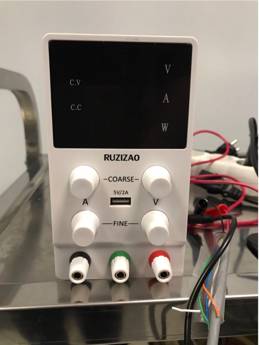
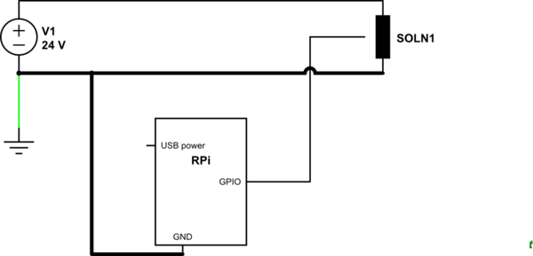
Set-Up 2:
Outcome:
the valve was opening but according to the sound it is opening and closing all the time, even though the code switches between high and low in 1 sec
diggin deeper into it: we put the GPIO constantly to high and later constantly to low, but the valve keeps on closing and opening with same speed, same sound, independently of the status of the GPIO!
we also reduced the 33kOhm to 22kOhm, no change
I'm very happy about every hint or suggestion! Thank you in advance!!

