4
\$\begingroup\$

I have built a DDS (0-80MHz) with an FPGA (XC3S400) that I can program it for making almost any wave form (limited frequency by the wave form complexity). After weeks of struggling with making a suitable low pass filter for it, I realized that it is almost impractical to build a near perfect analog filter that can remove all high frequency images (Nyquist) + all low frequency aliases (photos of the results here; hindrances made by low frequency aliases in DDS, figure-1 here).

Now I want to turn into a low pass (or preferably tunable band pass) digital filter but I really have not time for learning DSP from the scratch. I searched some major companies (Analog Devices, Texas Instruments,...) for a dedicated digital filter product but my search always redirects to DSP products.

I want to know if there are dedicated digital filters with a simple interface (for example, frequency selection by a micro-controller interface or something?). For example, sending the desired filter behavior via a serial/parallel word to the device and it works with that.

Edition:

I realized from the answer below that I can use the current FPGA for my purpose. I tried 2 approaches: 1- DDS > DAC > ADC > FIR (FPGA ) > DAC. this makes again aliases related to the DAC. 2- DDS > FIR ( no external ADC ) > DAC. This is not bad but the problem with aliases remains to some extend. I am looking for a good resource / method of thinking for this problem ( the easiest perhaps ! )

\$\endgroup\$
5
  • 1
    \$\begingroup\$ Unless I'm missing something, the aliases are a product of your SCOPE, and not your DDS. \$\endgroup\$ Commented Nov 25, 2013 at 19:23
  • \$\begingroup\$ @ScottSeidman No, finally I found it was a combination of all : scope + low frequency aliases , inherent to "Real world DDS" ( the second link provided in the question ) + bad ground line passing from FPGA instead of the dedicated pins + bad prototyping PCB design +...... and possibly many many other things that come into the account in high frequencies ( event perhaps the Martians ! :) ) !! \$\endgroup\$
    – Aug
    Commented Nov 26, 2013 at 8:02
  • \$\begingroup\$ I'm not sure I understand your question. What are you distinguishing between when you talk about "high frequency images" and "low frequency aliases"? Can you share the spectrum of your signal, showing what you mean by these two components? \$\endgroup\$
    – The Photon
    Commented Nov 27, 2013 at 19:19
  • \$\begingroup\$ @ThePhoton a link is provided in the question ( the first "here" ) or also: electronics.stackexchange.com/questions/91616/… \$\endgroup\$
    – Aug
    Commented Nov 28, 2013 at 19:36
  • \$\begingroup\$ @Aug, at your linked page, I don't see which features you are calling "low frequency aliases" and which features you are calling "high frequency images". Also you say above your problems are caused by a combination of several things including "bad ground line" and "bad prototyping PCB design." You absolutely must fix these two problems and show us the results before we'll be able to distinguish whatever problems you have with aliasing. \$\endgroup\$
    – The Photon
    Commented Nov 29, 2013 at 17:05

2 Answers 2

3
+250
\$\begingroup\$

Such products definitely exist, but it will be difficult for you to find a product which will fit into your project requirements precisely. For an audio frequency digital filters you can check out QuickFilterTech. For higher radio frequencies (>1GHz) Hittite comes to mind.

However, if you need to operate in the smaller 10s of MHz range, you will probably have to do what most people do: get yourself a smallish DSP or FPGA and use vendor supplied tools to generate a filter firmware (all major vendors have those; parametric design with GUI wizards and pictures supported).

In fact, the best (and most often used) contemporary approach for a single chip embedded design may be just this: FPGA implementing both the MCU and digital filter in the same firmware.

Update

Just noticed that you've already got a Spartan FPGA in your project. You can use Xilinx FIR compiler to generate a fixed filter out of the box (and use frequency shifter to do the tuning) or you can research some of the approaches for tunable filter implementation in the FPGA (some are not very difficult, plenty of publications around).

\$\endgroup\$
3
  • \$\begingroup\$ Thank you for the good suggestion. I just got a bit confused. I just made a FIR module ( IP CORE) . It has a [0..15] bit input and [0..36] bits output and as FPGA has no ADC, how should I use it? one idea is: DDS -> DAC ( a third party and outside the FPGA which makes aliases ) -> ADC -> FIR -> DAC ( again, without aliases) or simply I can use just one DAC ( DDS-> FIR -> DAC ). \$\endgroup\$
    – Aug
    Commented Nov 26, 2013 at 7:56
  • \$\begingroup\$ Don't think in analog terms, it's all digital. :) \$\endgroup\$
    – oakad
    Commented Nov 28, 2013 at 4:51
  • 1
    \$\begingroup\$ For the crudest possible approach you can take the DDS pulse train and connect it to the MSB of the FIR's input (was not this you wanted to do with the DAC/ADC?). The output of FIR will then resemble a sine wave. If this is your primary goal, there are filter topologies which are particularly suitable for pulse train to digitized sine wave conversion (but bear in mind, that you need to run the FIR at a sufficiently higher clock). \$\endgroup\$
    – oakad
    Commented Nov 28, 2013 at 4:57
2
\$\begingroup\$

Digital filtering sounds like the only way to achieve what you want and my twopenneth isn't much but here goes.

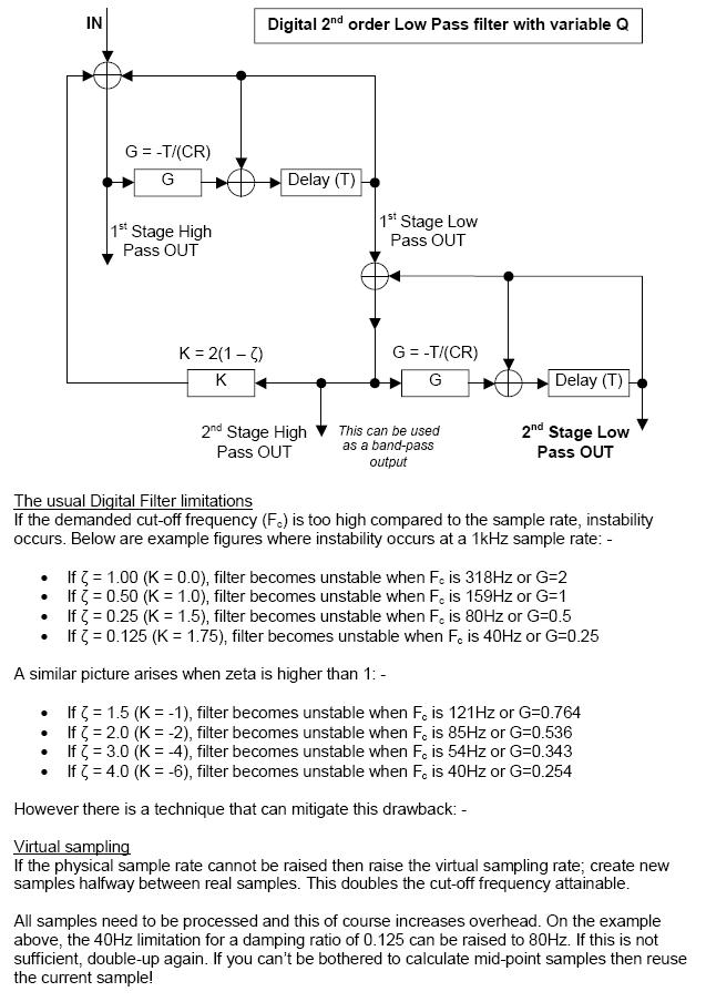
There are basic 2nd order digital filters that are good and reasonably simple but they rely on a fair bit of oversampling to achieve bandwidths that are close to the basic sample rate. Oversampling can be achieved by taking two consecutive basic samples and creating samples in between. I'm saying this because these are the only digital filters that I know of (in my limited capability on this subject) that might work.

Here's one that is based on 1kHz sampling and mentions the creation of oversamples to achieve stability beyond the 300Hz limit without oversampling. If you have samples already at a rate of 1GHz then this type of filter would work up to maybe 200MHz: -

enter image description here

\$\endgroup\$

Your Answer

By clicking “Post Your Answer”, you agree to our terms of service and acknowledge you have read our privacy policy.

Not the answer you're looking for? Browse other questions tagged or ask your own question.