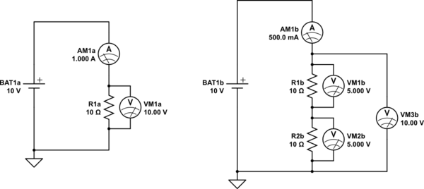
simulate this circuit – Schematic created using CircuitLab
The battery produces a potential difference (voltage) across it of 10V. That's its job, to ensure that one of its terminals (the positive) is 10V higher in potential than the other, regardless of what's connected to them.
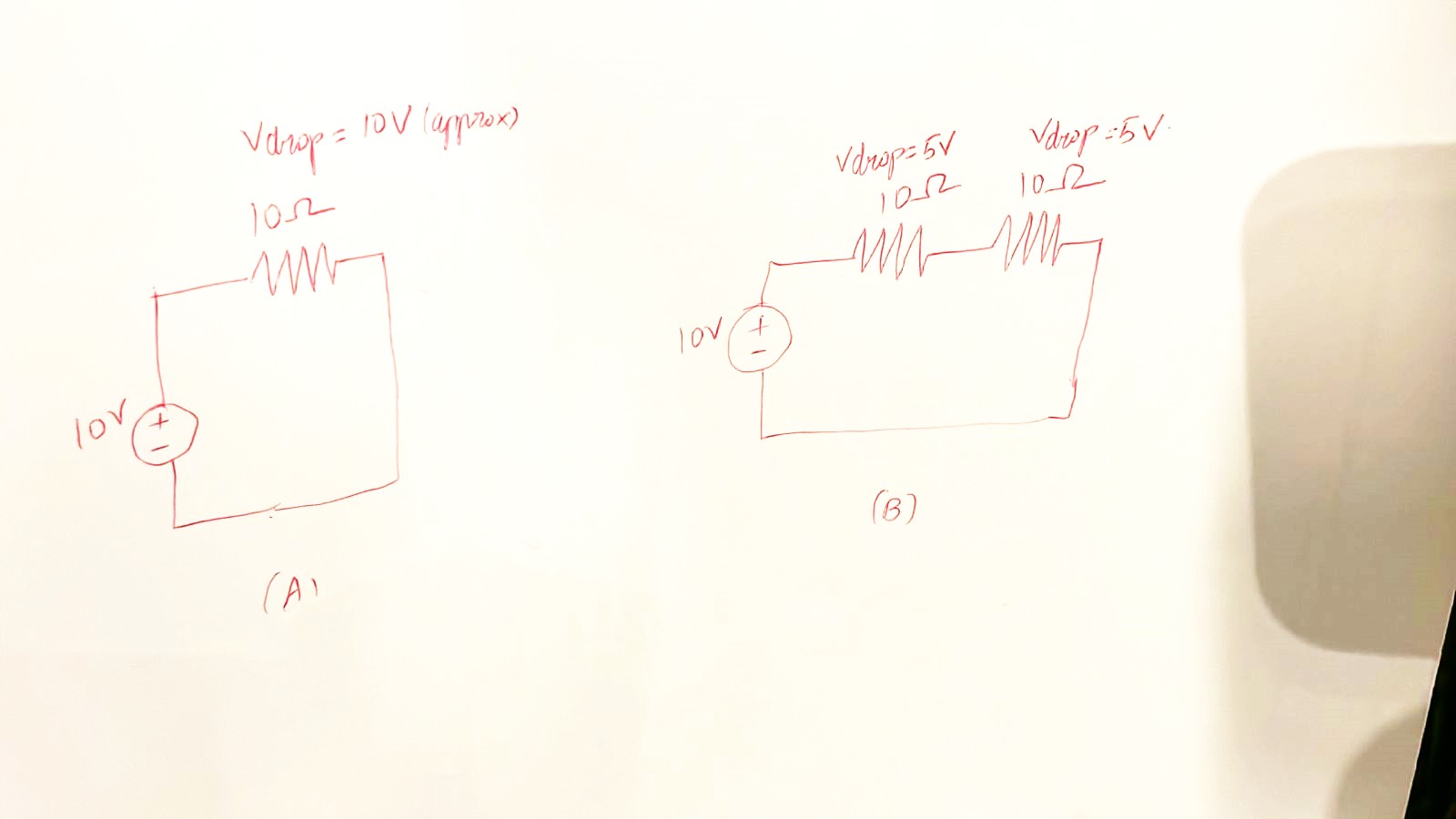
In the left circuit the battery has 10Ω of resistance, in the form of R1a, connected between its terminals. The battery therefore ensures that at all times, there is a difference in potential of 10V between the two ends of the resistor.
It's not so much that the resistor is "dropping" 10V, it's that the battery is forcing there to be 10V across it.
That's the short answer to your question; the battery's job is to maintain 10V volts across the resistor, and there's nothing (almost) anyone can do about that. That's why there's a potential "drop" (AKA "difference" in potential) of 10V between the resistor's two ends, as shown by VM1a.
It's not a very satisfying answer. I would rather ask why the two resistors in the right-hand circuit each have a potential difference of only 5V across them (see VM1b and VM2b)?
Since I already explained the battery's role here is to maintain 10V between its own two terminals, it's no surprise that the total potential difference between the top of R1b and the bottom of R2b should still be 10V. You can see that shown on voltmeter VM3b, keep that in mind.
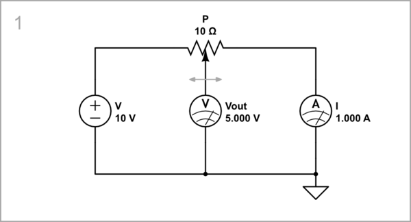
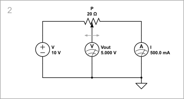
Notice the current that's flowing around the loop, shown on ammeters AM1a and AM1b. On the left it's 1A, on the right it's 0.5A. The reason that the right hand circuit produces half as much current is that there's twice as much resistance in the path between the battery terminals. In other words, on the left the battery's 10V is being applied across a total resistance of 10Ω, but on the right the resistance is 20Ω, the sum of the two individual resistors. According to Ohm's law we can calculate what the resulting currents should be:
$$ I_{LEFT} = \frac{V_{BAT1a}}{R_{1a}} = \frac{10V}{10\Omega} = 1A $$
$$ I_{RIGHT} = \frac{V_{BAT1b}}{R_{1b} + R_{2b}} = \frac{10V}{10\Omega + 10\Omega} = 0.5A $$
Again with Ohm's law, we can find out what voltage would appear across one of the individual resistors, say R1b:
$$ V_{R1b} = I_{RIGHT} \times R_{1b} = 0.5A \times 10\Omega = 5V $$
The 10V of BAT1b is shared equally between the two resistors R1b and R2b (5V and 5V), because the current flowing has halved, which is a more satisfying reasoning.
Update
Here's why voltage across each resistor in a potential divider is independent of current. Take a "chain" of resistors R1, R2 and R3, connected in series between some potential difference VS:
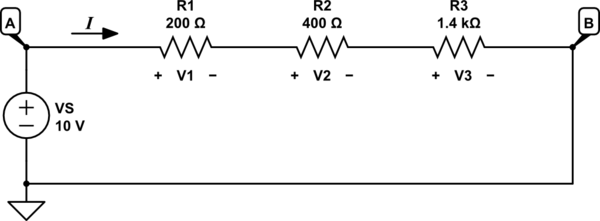
simulate this circuit
Kirchhoff's Current Law (KCL) tells us that since there are no branches for current \$I\$ in this loop to leave or enter anywhere, current must be the same everywhere, in every resistor and in the voltage source VS.
Kirchhoff's Voltage Law states that all the potential rises and falls that are encountered around any loop must sum up to zero, in the same way that after a walk around town, in a loop that brings you back to where you started, you must always end up at the same elevation (above sea level, for instance) at which you started.
Remembering that current always flows inside a resistor from the end with higher potential to the lower potential end, we travel around the loop. You could start/end at any node, and go in either direction, and the maths would still work out, but here I'll go clockwise from A, through the resistances to B, then back across VS to return to A.
First we cross R1, and experience a potential decrease of V1, then R2 and R3, each incurring a decrease of potential. In the KVL expression we denote potential decreases as subtractions, and increases as additions, as you would treat climbing or descending stairs or hills or valleys on your walk. After traversing the resistances to arrive at B, the last step is over VS, where you find an increase (addition) of \$V_S = 10V\$, and at which point you should have returned to the same potential you started at. This implies an overall potential change of zero volts:
$$ -V_1 -V_2 -V_3 + V_S = 0V $$
A slight rearrangement might reveal a more familiar relationship, and make more sense:
$$ V_1 + V_2 + V_3 = V_S $$
If you recall, I said the battery's job is to impose a fixed potential difference across something. This last expression is demonstrating this more formally. The voltage source VS represents our battery, which according to KVL is ensuring that at all times the sum of all potential differences in the resistor chain stays 10V.
Now we employ Ohm's Law, to bring together our conclusions from KVL and KCL. Ohm's law permits us to relate voltage across a resistor, to the current through it:
$$
\begin{aligned}
V_1 &= I \times R_1 \\
V_2 &= I \times R_2 \\
V_3 &= I \times R_3 \\
\end{aligned}
$$
Substituting those voltage "drops" into the KVL equation, we can get reveal current I:
$$
\begin{aligned}
I\times R_1 + I\times R_2 + I\times R_3 &= V_S \\ \\
I(R_1 + R_2 + R_3) &= V_S \\ \\
I &= \frac{V_S}{R_1 + R_2 + R_3}
\end{aligned}
$$
At this point you may notice that this looks very much like Ohm's law again, \$I=\frac{V}{R}\$, but instead of individual resistances, we have the sum of all of them. We've "accidentally" shown that total resistance of a chain of series-connected resistors is the sum of the individual resistances. It is the reason I was able to make the following statement from my original answer:
$$ I_{RIGHT} = \frac{V_{BAT1b}}{R_{1b} + R_{2b}} = \frac{10V}{10\Omega + 10\Omega} = 0.5A $$
With an expression for \$I\$, we are able to plug that into the Ohm's law equations for each individual resistance:
$$
\begin{aligned}
V_1 &= I \times R_1 \\ \\
&= R_1\frac{V_S}{R_1 + R_2 + R_3} \\ \\
&= V_S\frac{R_1}{R_1 + R_2 + R_3}
\end{aligned}
$$
The voltage across the other resistors have a similar form:
$$
\begin{aligned}
V_2 &= V_S\frac{R_2}{R_1 + R_2 + R_3} \\ \\
V_3 &= V_S\frac{R_3}{R_1 + R_2 + R_3} \\ \\
\end{aligned}
$$
The voltages across the resistors is independent of current \$I\$, which doesn't appear at all in these last equations, in spite of having been instrumental in their derivation.
This same result is valid for any number of resistors. Your original question used two, and they were equal. If we call them \$R_1=R_2=R\$, then we have:
$$
\begin{aligned}
V_1 &= V_S\frac{R_1}{R_1 + R_2} \\ \\
&= V_S\frac{R}{R + R} \\ \\
&= V_S\frac{R}{2R} \\ \\
&= V_S\frac{1}{2} \\ \\
\end{aligned}
$$
If half of \$V_S\$ appears across one resistor, then the other half must remain across the other; the voltage \$V_S\$ is shared equally between them. There's no mention of resistance at all in that last equation, or current, and we can conclude that this always occurs if the resistances are equal, regardless of the actual resistance, and current will always be exactly the correct amount to bring about those conditions.

