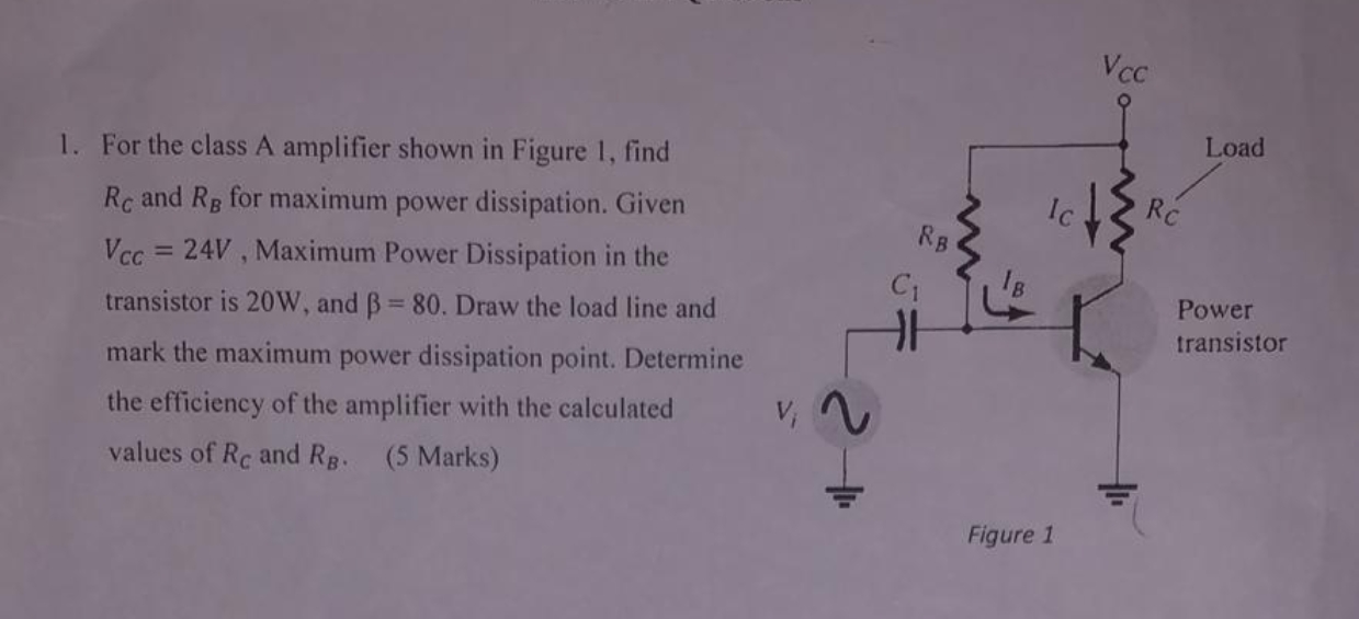
Assuming the question isn't otherwise just screwy (that it didn't arrive from a moment of madness by some instructor or student intern), the only possible inference I find that allows a unique answer is to assume it means finding \$R_{_\text{C}}\$ such that the specified BJT power dissipation cannot be exceeded, regardless of variations in collector voltage due to varying base drive.
Note: I don't believe the dissipation by the base-emitter junction of the BJT is to be included.
For any given \$R_{_\text{C}}\$ its load line is \$I_{_\text{C}}=I_{R_\text{C}}=\frac{24\:\text{V}-V_{_\text{C}}}{R_{_\text{C}}}\$.
Dissipation in the BJT is \$P_{\text{bjt}}=V_{_\text{C}}\cdot I_{_\text{C}}= V_{_\text{C}}\cdot\frac{24\:\text{V}-V_{_\text{C}}}{R_{_\text{C}}}\$. The maximum value here -- the worst-case situation for the BJT, given any particular \$R_{_\text{C}}\$ -- must be capped at \$P_{\text{bjt}}\le 20\:\text{W}\$.
The derivative of \$P_{\text{bjt}}\$ with respect to \$V_{_\text{C}}\$ will be zero at a maximum (or minimum) and a solution to this finds the maximum occurs at \$V_{_\text{C maxpwr}}=\frac12\cdot 24\:\text{V}=12\:\text{V}\$.
So in the worst case, \$I_{_\text{C maxpwr}}=\frac{20\:\text{W}}{V_{_\text{C maxpwr}}}=\frac53\:\text{A}\$.
So \$R_{_\text{C}}=\frac{24\:\text{V}-12\:\text{V}}{\frac53\:\text{A}}=7.2\:\Omega\$.
The value for \$R_{_\text{B}}\$ is a little more mysterious. But we can assume that the base-emitter junction will be less than \$1\:\text{V}\$ and therefore estimate a value of \$R_{_\text{B}}\approx \frac{24\:\text{V}-1\:\text{V}}{\frac1{80}\,\cdot\,\frac53\:\text{A}}\approx 1.1\:\text{k}\Omega\$ and not be far off.
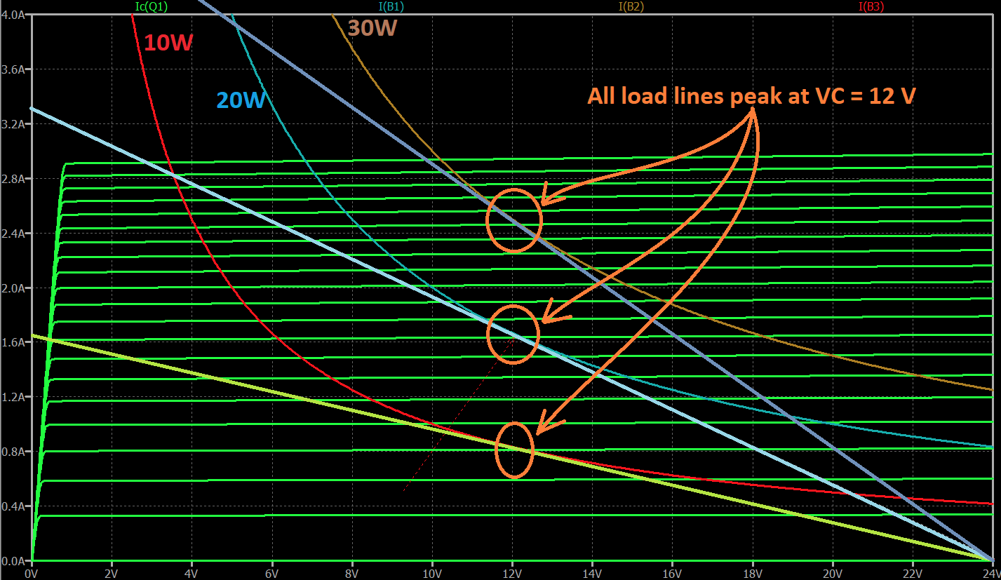
The intersection between the I-V load line of the collector resistor and the I-V curve allowed by the BJT's power limit must always intersect at \$\frac12V_{_\text{CC}}\$.
This is true in the general case as shown, using freely available SymPy:
var('vcc,vc,rc')
solve( Eq( derivative( vc*(vcc-vc)/rc, vc ), 0 ), vc )
[vcc/2]
Note that this result is completely independent of the collector resistor value.
For this case, with \$V_{_\text{CC}}=24\:\text{V}\$, I've illustrated the case with BJT I-V curves for power limits of \$10\:\text{W}\$, \$20\:\text{W}\$, and \$30\:\text{W}\$, together with the collector resistor load line that guarantees the BJT power dissipation isn't exceeded:

The collector resistor load line must intersect the BJT curve for it to be a solution, at all.
But in the case where the collector resistor forms a secant cut through the BJT curve, the two secant intersections show the two points where the maximum dissipation in the BJT is met. But everywhere between those two points will cause the BJT power to exceed its specification.
So only in the specific case where the resistor load line just touches the BJT I-V curve at one point (where the resistor load line is tangent to the allowable BJT I-V curve) is both a solution provided and also one where there are no points where the power limit is exceeded.
I've circled in orange the intersection for each of these collector resistor load-line tangents. They all fall on the case of \$V_{_\text{C}}=12\:\text{V}\$.
As they must.


