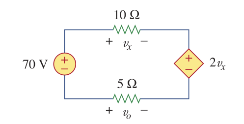
You'll usually always write KVL according to the annotated polarities, so that ultimately the sign of the calculated values will conform to those annotations, but there's a caveat which I'll explain later.
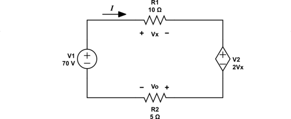
By that argument, as you go around the loop clockwise starting from the bottom of the 70V source, you will add annotated rises in potential, and subtract annotated falls in potential. First is a rise across the 70V source, then there's a fall in potential across 10Ω, then another fall across the dependent source, and finally a rise across 5Ω:
$$ 70 - V_X - 2V_X + V_O = 0 $$
Alternatively you can think of it purely in terms of additions, in the true spirit of KVL being a "sum of all voltages":
$$ (+70) + (-V_X) + (-2V_X) + (+V_O) = 0 $$
The problem you will encounter is that one of those resistances is annotated with a polarity which conflicts with passive sign convention. Which one depends on the annotated direction of current, which is not shown in your schematic.
A resistor's current always enters the terminal with the higher potential, and leaves from the lower potential end. If you label that current in this simple loop as \$I\$, flowing clockwise, then you can see that the polartiy markings for the 5Ω resistor break that convention. You can expect the final voltage amount that you derive for that resistor to have the wrong sign.
Either you keep this in mind, and correct the sign after solving all the equations, which is just asking for trouble if you forget, or you correct the polarity annotations (to conform with passive sign convention) prior to building the KVL equations. This latter approach is always my preferred one.
A third solution, if your professor insists on keeping those marked polarities as they are, could be to annotate the schematic with two currents, \$I_1\$ going clockwise, and \$I_2\$ anti-clockwise, and set \$I_1=-I_2\$, but that's just crazy, because it adds an unnecessary variable.
To illustrate fixing annotations that don't conform to passive sign convention, this is how I would draw the schematic:

simulate this circuit – Schematic created using CircuitLab
Given that current \$I\$ travels to the right through R1, and to the left through R2, and is therefore entering those resistors at the terminals marked with the higher potential, this now conforms to passive sign convention. Now the KVL equation (obeying the new annotations) looks like this:
$$ 70 - V_X - 2V_X - V_O = 0 $$
That's the same as your first equation, so you could argue that this was the correct application of KVL all along. You might say that by ignoring the original marked polarity for R2, and sticking with the reality that current travels to the left through it, you've mentally swapped its polarity anyway.
I would argue though, that instead of having to remember to flip the sign afterwards, so that values agree with reality, and a "flawed" schematic, it's always better just to annotate things correctly in the first place. Always mark resistors with a "+" where annotated current enters, and all the ambiguity goes away.
The same goes for diodes, capacitors and inductors. You can use the diode equation in your KVL equations, and you can use \$\frac{dV}{dt}=\frac{I}{C}\$ and such, but always take care to annotate the schematic in such a way that conforms with reality, with passive sign convention. With this convention, in which annotated current enters where a component is marked with "+" (or the diode's anode), you avoid a lot of headaches.
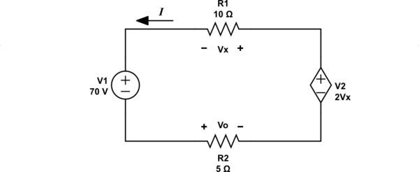
RussellH's comment highlights my failure to point out that you are not expected to know current direction or voltage polarity ahead of time. Let me illustrate with this next schematic:

simulate this circuit
I changed current direction, but to remain in conformance with passive sign convention, I also changed polarity of voltage across both resistances. Now the KVL is:
$$ 70 + V_X - 2V_X + V_O = 0 $$
When I solve the equations, I will still obtain the correct amounts and signs, because I am still obeying passive sign convention, but I might find some negatives, which simply tell me I guessed polarities wrong.


