2
\$\begingroup\$

I'm a computer programmer by trade who has taken an interest in Arduino with the hopes of eventually producing a particular hardware project that has captured my hobby/side-business interest.

I understand only a very little bit of electronics and am trying to fix that. Please be gentle if my questions are very basic or silly. I'm really trying to understand some new concepts.

I'm reading "Introduction to Electronics" 5th Edition by Earl D. Gates. I'm really enjoying it and finding that it lays out material in a structured and helpful way. It was well worth the $1.00 I paid on Amazon! ;-)

I'm reading through a section that deals with Ohm's Law and Kirchhoff's Current Law, and I'm struggling to understand some concepts.

I can understand (or at least do the calculations for) the I = E / R equation. It's basic math, so that's not hard. The explanation of what figures in a circuit go where is also fairly easy to understand.

The book has drawn circuits with ? values for various parts of the circuit (voltage, current or resistance), and I am able to successfully solve for the missing values. Not too hard, actually.

What is currently confusing me is "voltage drop". I have a question that gives the following circuit:
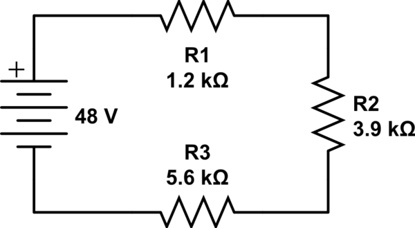
schematic

simulate this circuit – Schematic created using CircuitLab

The question asks, "How much voltage is dropped across resistor R2 in this circuit?"

So, first, we solve for current, which calculates to I = 4.5mA. (Actually, 4.485981308mA.)

Then, knowing that current is the same for the entire circuit, we can set up the following equation:

I2 = ER2 / R2 (which, why is it suddenly ER2, not just E?)

0.0045 = E / 3900

Therefore, voltage drop is 17.55V.

But what does this mean?

Using the same calculations, voltage drop for the different pieces of the circuit are:

Resistor 1: 0.0045 * 5600 = 25.20V
Resistor 2: 0.0045 * 3900 = 17.55V
Resistor 3: 0.0045 * 1200 = 5.40V

And those total to 48.15V, so our math is close but has minor rounding issues.

But, again, what does this mean?

Does it mean that tapping into the circuit between resistors 1 and 2 would give me 22.8V (48V - 25.2V)?

If I have a sensitive electronic component that accepts 3V-6V, would it be safe to draw this power from the circuit after resistor 3?

Am I even close to a proper understanding?

What I'm interested in is working with some 3.3V components, starting with with an input voltage that's maybe 3.7V (LiPo), maybe 5V (USB), maybe 9V, etc. I understand that my Arduino Uno already has power regulators that output 3.3V @ up to 50mA, but HOW does it do that?

It says it can accept 6-20V (but USB is 5V!), and somehow it deals with all of that excess voltage to provide a steady, regulated 3.3V. What dark magic is taking place here? ;-)

I realize that there are many, many components out there that will "just work" to give me the electrical output I desire (I've been playing with a few, like the LM317), but I'd like to really understand what's going on, not just know which component works. Thus far, all attempts to actually get the LM317 to work have failed, because I apparently have a serious lack of understanding on this issue.

Anyway, I really appreciate if you've read this far. Thanks for any help!

\$\endgroup\$
6
  • 1
    \$\begingroup\$ First, when you're talking about a circuit, press Ctrl+M and draw it so we can understand what you're talking about. Second, you should really break this up into multiple questions. The LM317 part is not related to the first half. \$\endgroup\$
    – Matt Young
    Commented Feb 4, 2014 at 15:04
  • \$\begingroup\$ Would it help if, instead of "voltage Drop", you said "Voltage developed across the resistor"? - Same thing, but different point of view. \$\endgroup\$ Commented Feb 4, 2014 at 17:49
  • \$\begingroup\$ @MattYoung Actually, it IS one progressive question. My understanding may be flawed, but I'm trying to understand voltage drop and how it may or may not relate to voltage regulators. This is my first post, so didn't know about Ctrl+M. Will fix. \$\endgroup\$
    – mbm29414
    Commented Feb 4, 2014 at 18:26
  • \$\begingroup\$ OK, so the circuit-builder tool is AWESOME!!! \$\endgroup\$
    – mbm29414
    Commented Feb 4, 2014 at 18:33
  • 1
    \$\begingroup\$ @mbm29414: The circuit you gave is just an exercise to demonstrate Ohm's and Kirchoff's laws, and voltage dividers. If you connect a load of any kind across one resistor, you will have to re-calculate the voltages, as the current drawn by the load will upset things. If you connect another 3K9 resistor across R2, you effectively have 1.95K in that position. Voltage dividers such as this are very useful, but you must allow for any currents drawn from them when calculating the resistor values. \$\endgroup\$ Commented Feb 4, 2014 at 18:57

2 Answers 2

1
\$\begingroup\$

You are basically on the right track with your understanding of Ohms Law and Kirchoff's Law.

The concept of "voltage drop" can sonfuse beginners (I know it did that to me). As one responder stated Kirchoff's Law can be legitimately restated to mean that the "voltage drops" across the passive elements in a circuit path must equal the voltage applied to that circuit by the voltage source(s). A "passive element" is an element which does not produce any voltage of its own - resistors are the prime examples.

In your example you have three resistors, Kirchoff says that the 48 volts must be distributed (dropped) across those three resistors. So, the current running thru the three resistors will naturally equalize at a value where that becomes true. Ohms Law tells you the value of that current. Kirchoff's Law and Ohms Law must be "met" simultaneously for equilibrium to exist. Everything has to "play" together: the voltages across the resistors have to add up to 48 volts AND the current-to-voltage relationship defined by Ohms Law must also exist. Mathematically, there are 4 unknowns - the current and the three voltage drops. If you are mathematically inclined you could write a group of simultaneous equations to solve the problem. If you are just trying to get a feel for how it works, you can apply Ohm's law piecemeal and intuitively based on the two principles (Ohms Lay & Kirchoff's Law).

Further, you can change the resistor value to any values you like, this will merely change the equilibrium and you would end up with a different current and three different voltage drops across the resitors, but you would still be adhering to Kirchoff's Law (all the drops would have to add up to 48 volts) and Ohms Law (the current is such that the voltage across each resistor allows Kirchoff's Law to be satisfied) - harmony!

Of what practical use is a circuit like this? Ummm, that depends on how you define "practical"? What practical use is a push-up to a baseball player? He's not gonna go onto the game field and do push-ups. What practical use is a machine screw and nut in your hand? You can twirl the nut up and down the screw thread for fun. But the real use comes into play when you use that screw and nut to mount a hanger hook onto a work bench, or to hold an axle to a car frame.

Your circuit taken on it's own simply illustrates the two principles involved. But if you teamed it up with an op-amp or comparator you would be using the two intermediate voltages to perform a useful task in a more complex circuit. E.g. they might provide voltage threshold values in a comparator circuit, or reference levels in an op-amp-based amplifier.

The thing about Ohms Law and Kirchoffs Law (and let's not forget Nortons Law for currents) is that they are pervasive at all levels of electronics. They are used in every electronic discipline - analog, digital, RF, television, audio, etc - over and over and over. You will not go far in any of these fields without a firm, gut-level understanding of these "laws". And they are indeed the "Laws of Electronics" - nothing in electronics works unless it follows these laws - believe me, I've tried to break them numerous times and they have always succeeded in breaking me!

\$\endgroup\$
1
  • \$\begingroup\$ Thanks for your answer! Nice to know I'm not the only beginner for whom this is a little bit confusing. I'm content to learn the Laws for now and keep learning so I can understand their implementation. Thanks! \$\endgroup\$
    – mbm29414
    Commented Feb 5, 2014 at 12:37
5
\$\begingroup\$

your first question:

... Therefore, voltage drop is 17.55V.

But what does this mean?

Using the same calculations, voltage drop for the different pieces of the circuit are:

Resistor 1: 0.0045 * 5600 = 25.20V Resistor 2: 0.0045 * 3900 = 17.55V Resistor 3: 0.0045 * 1200 = 5.40V

And those total to 48.15V, so our math is close but has minor rounding issues.

But, again, what does this mean?

This referes to the Kirchhoff voltages's law. The sum of all voltage drops in series circuit must be equal to the voltage applied (this is not entirely correct, but serves the proposed circuit and avoid complications).

Does it mean that tapping into the circuit between resistors 1 and 2 would give me 22.8V (48V - 25.2V)?

I fail to understand this question. The voltage drop obtained for each resistor is the voltage that you can measure with a voltmeter conected to the resistor pin's.

If I have a sensitive electronic component that accepts 3V-6V, would it be safe to draw this power from the circuit after resistor 3?

Definitely not. Any circuit connected to the shunt, completely modifies the behavior of the original circuit, and hence the original voltage drop.

... It says it can accept 6-20V (but USB is 5V!), and somehow it deals with all of that excess voltage to provide a steady, regulated 3.3V. What dark magic is taking place here? ...

The voltage regulator is a retrofitted system, i.e. when a circuit is connected to the regulator's output, an internal circuit operates to maintain a stable output voltage.
The difference between the input voltage and the output is absorbed by the regulator, as having a "variable resistor". According to the connected circuit, the internal regulator circuit "set" the value of this "variable resistor" (actually it is a transistor, for a linear regulator) so that the voltage is maintained within a specified range.

Voltage regulators are a whole specific field of application in electronics. There are many types. Particularly, the LM317 regulator is a linear regulator. Implements a transistor as a regulating element between the input voltage and the output voltage. The control of this transistor lets adjust its voltage drop, according to the circuit you want to feed.

\$\endgroup\$
4
  • 1
    \$\begingroup\$ Good answer, but I would say the regulator is a "feedback" system..."retrofitted" sounds like the wrong word to me. \$\endgroup\$
    – Justin
    Commented Feb 4, 2014 at 16:36
  • \$\begingroup\$ @Justin Yes! sorry for my English.... :( I hope to improve soon \$\endgroup\$ Commented Feb 4, 2014 at 16:40
  • \$\begingroup\$ @Tinchito You said "the voltage drop obtained for each resistor is the voltage you can measure with a voltmeter connected to the resistor's pins". I know this is a basic/simple question, but what does that mean? Practically, what does that knowledge tell me about setting up a circuit? \$\endgroup\$
    – mbm29414
    Commented Feb 4, 2014 at 18:34
  • \$\begingroup\$ The voltage, is (like) a "force" that push the electric charges (electrons) through the resistor, i.e., the voltage sets the current. The voltage value is a measure of how hard is the passage of electric charges through the resistor. A higher value of the resistor, the higher voltage value to establish the same current. This is an interpretation of Ohm's law. \$\endgroup\$ Commented Feb 4, 2014 at 18:47

Not the answer you're looking for? Browse other questions tagged or ask your own question.