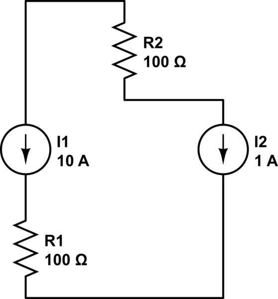
As stated in an earlier comment the first circuit is not solvable because its a simple series circuit and therefore must have the same current everywhere It can't be both +10A and -1A.
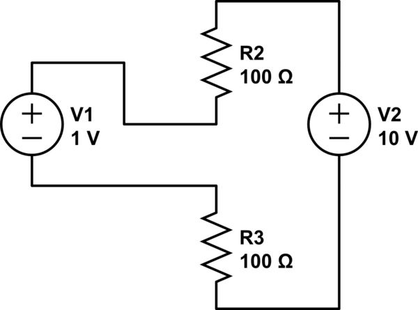
Now we come to an analysis of the second circuit.
It is also a series circuit so must have the same current everywhere.
From Kirchhoff's voltage law we know that if you follow any closed loop all the way round the voltages must sum to zero.
$$10 \text{ volt} + I \cdot 100 \ \Omega - 1 \text{volt} + I \cdot 100 \ \Omega = 0 \text{ volt}$$
$$9 \text{ volt} + I \cdot 200 \ \Omega = 0 \text{ volt} \Rightarrow I = - \frac{9}{200} = - 45 \text{ mA}$$
The minus sign just implies that the current is in the opposite direction to the one I originally guessed.
Working from the bottom of the diagram up the bottom node is 0V the voltage at the top of the bottom resistor is \$ 0.045 \text{ A} \cdot 100 \ \Omega = 4.5 \text{ volt}\$
The voltage at the bottom of the top resistor is \$ 4.5 \text{ volt} + 1 \text{ volt} = 5.5 \text{volt}\$ with 10 volt at the top node with a current of 45mA circulating counter clockwise around the loop.


