2
\$\begingroup\$

I'm driving some 12v fan motors from a microcontroller using ULN2003A Darlington array. Both total wattage and per-channel wattage are way below ULN2003a limits. Still, I found that when PWM duty cycle is below 20%, ULN2003a starts to get really hot (can't touch with a finger). At higher PWM duty cycle temperature is much lower.

Update: Fans draw around 0.2A each, and the PWM frequency is 32 kHz currently. The capacitors are there to reduce the audible noise (I was using lower PWM frequency initially).

Am I correct in suspecting that the heat source is the flyback diodes, and not the darlingtons?

I'm thinking of adding some external flyback diodes across the motor coil. Is this the corect thing to do in this situation? I have some 1N5818DICT on hand (Schottky diode 30V 1A, Recovery < 500ns). Will such diode be ok, or I I need something special?
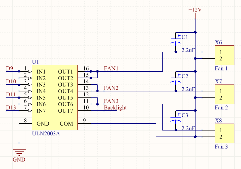
enter image description here

\$\endgroup\$
5
  • \$\begingroup\$ Darlington switches are not a good idea here. \$\endgroup\$ Commented Jun 29, 2014 at 17:36
  • 1
    \$\begingroup\$ Try removing those 2.2uF caps too. You can't sensibly PWM directly into a capacitor, that's asking for trouble. What PWM frequency are you using and what is the expected fan current on 12V dc? \$\endgroup\$
    – Andy aka
    Commented Jun 29, 2014 at 18:03
  • \$\begingroup\$ @Andyaka: Fans draw around 0.2A each, and PWM frequency is 32kHz now. The capacitors were put there to reduce audible noise from fans, initially the PWM frequency was much lower. \$\endgroup\$
    – haimg
    Commented Jun 29, 2014 at 18:46
  • \$\begingroup\$ I am new to microcontrollers; and found the answers interesting and informative. however isn't the ULN2003 rated for 5V; and it's the ULN2004 rated for 6 - 15V ? Just a thought...maybe driving 12V fans is too tasking for a 5V device. I found a datasheet on Darlington's here: <verical.com/pd/…> Or is it necesssary to run an ULN2003 because it's TTL ? Thanks, \$\endgroup\$
    – user69385
    Commented Mar 7, 2015 at 14:41
  • \$\begingroup\$ The voltage rating that you are referring to for the uln2003 & uln2004 are for the INPUT (control) voltage. These are open-collector devices and the maximum voltage they can switch is the same for both devices. \$\endgroup\$ Commented Mar 7, 2015 at 15:32

2 Answers 2

7
\$\begingroup\$

PWM frequency is 32 kHz so that's a period of about 32 us and half that time the transistor will be dumping energy into charging up those capacitor. It'll be doing it totally inefficiently too so maybe half that energy again is wasted in transistor heat.

Capacitor acquired energy is \$\dfrac{CV^2}{2} = \dfrac{2.2 \times 10^{-6}\times 144 }{2}\$ = 0.158mJ

BUT because charging the cap is done totally inefficiently, at a guess, the transistor will throw away just as much energy. It does this 32,000 times per second so that's a power of about 5 watts per transistor.

Now I may have over-egged this a bit by assuming that each 2.2uF would become totally discharged in one cycle of PWM but I'd wager that each transistor is doing over a watt just driving these capacitors back to full charge (32,000 times per second). Get rid of the caps and if you still have problems with noise then come back and tell us.

The lower the duty cycle the worse this will be because there will be a longer time for these caps to discharge and hence inefficiently re-acquire more of their 0.158mJ when the transistor switches back on again.

\$\endgroup\$
3
  • \$\begingroup\$ Thanks for your answer. Capacitors were indeed not needed and harmful. I removed them. The situation has improved, but just. E.g. ULN2003A is not scorching hot, just very hot. And of course once I raise the pwm duty cycle, it becomes barely warm. \$\endgroup\$
    – haimg
    Commented Jun 30, 2014 at 22:10
  • \$\begingroup\$ @haimg so now maybe you should consider replacing the ULN with something that is a more efficient driver. These are darlingtons and are always going to drop about 1V when conducting 200mA - that's 200mW per channel. You need to use MOSFETs for this to run cool. Like this google.co.uk/… - it has 0.5 ohms on resistance therefore only 20mW per channel (TPIC2701) or individual mosfets. \$\endgroup\$
    – Andy aka
    Commented Jul 1, 2014 at 7:18
  • \$\begingroup\$ Be aware that there may also be bypass capacitors inside the fans. Same issue as above. The fix is to install inductors between the driver output & fan input. \$\endgroup\$ Commented Mar 7, 2015 at 15:34
3
\$\begingroup\$

At high duty cycles — which means high fan speed — the back EMF of the fan keeps its capacitor from discharging significantly. However, at low duty cycle values, the capacitor discharges most of the way.

In the worst case, it discharges completely, which means that it needs to be recharged each time the Darlington turns on. The charge is 2.2 µF × 12 V = 26.4 µC. Done 32,000 times per second, this represents an average current for the capacitors alone of 845 mA.

Keep in mind that VCE for these Darlingtons is on the order of 1.5V at this current level, so the transistor pair for each motor is dissipating about 1.3 W.

When you increased the PWM frequency, you should have reduced the capacitor values proportionally. You should probably get rid of them altogether.

\$\endgroup\$

Your Answer

By clicking “Post Your Answer”, you agree to our terms of service and acknowledge you have read our privacy policy.

Not the answer you're looking for? Browse other questions tagged or ask your own question.