1
\$\begingroup\$

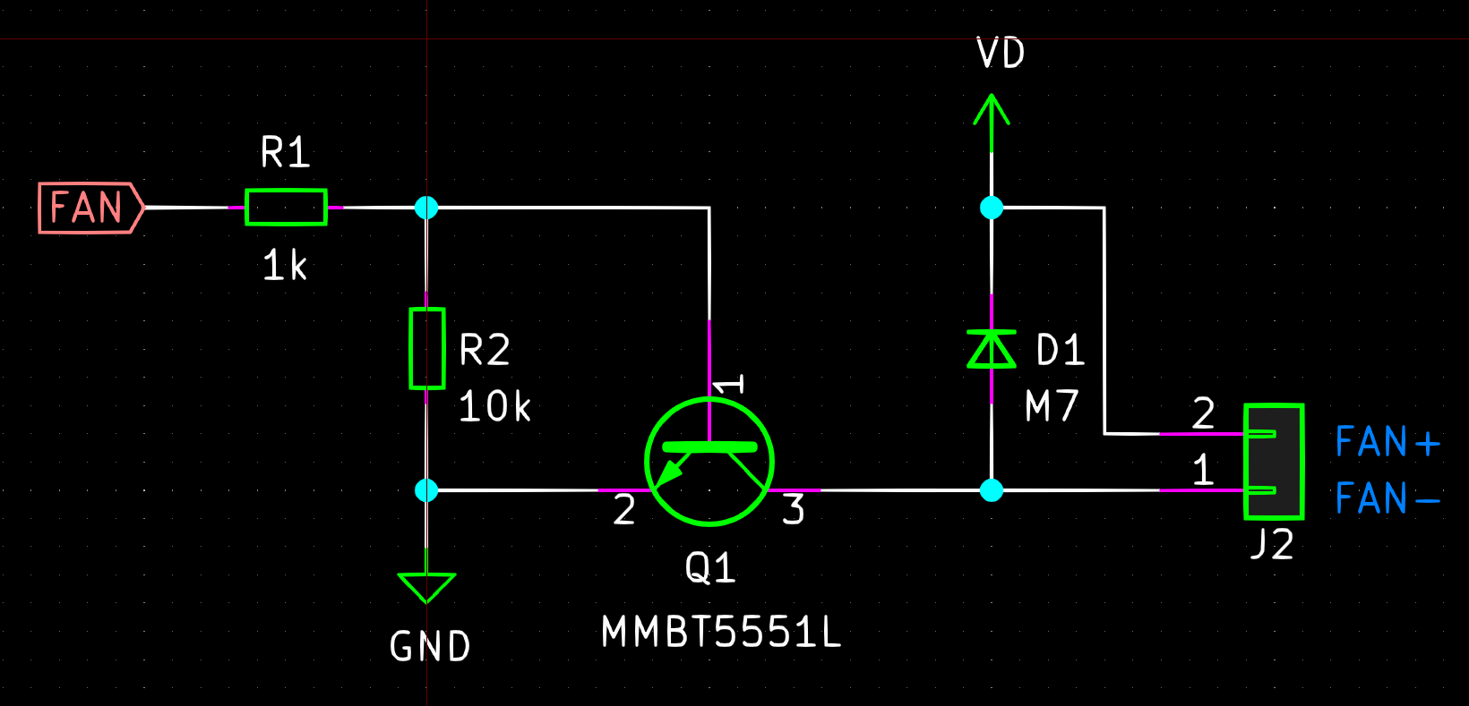
Sub-schematic

  • VD = 14.8 VDC
  • The load is a 1.5W/12V fan

When the "FAN" input is DC On/Off, it works fine - even with no series resistor to limit the extra current.

When "fan" input is 5V PWM (50 to 70% duty cycle,) it works for seconds then thr transistor fails with collector-emitter shorted.

The diode is M7. I tried an S310 Schottky with the same result.

I tried several PWM frequencies from 7K to 70 kHz.

The transistor VCE is rated for 150V. The flyback diode breakdown voltage is OK.

On the oscilloscope there is nothing abnormal.

The PCB layout is as normal with enough ground plane from emitter to the power supply.

I used such circuit in many projects before with no issues.

\$\endgroup\$
3
  • \$\begingroup\$ What is the motor's DC resistance? Did you work out the startup current? \$\endgroup\$
    – Transistor
    Commented Jul 2, 2021 at 18:42
  • \$\begingroup\$ Motor's DC resistance about 60Ohms .. The driving transistor should handle up to 600mA .. The Motor's current doesn't exceed 200 mA .. It all works in On/Off mode but not in PWM with much lower currents !!! \$\endgroup\$ Commented Jul 2, 2021 at 18:47
  • 1
    \$\begingroup\$ I bet there is more than just windings and a commutator inside that fan. I suggest skipping this altogether, and using a 3-wire fan with built-in PWM control. \$\endgroup\$
    – rdtsc
    Commented Jul 2, 2021 at 19:15

1 Answer 1

1
\$\begingroup\$

The problem is your fan is more than just a motor, it has a circuit in it which converts the DC into AC to drive the brushless motor windings. It probably has a large smoothing capacitor across the power input keep the voltage stable while the motor draws pulses of current.

When you apply PWM the capacitor in the fan draws a very high current as it charges up, then discharges during the PWM 'off' period. As result the transistor passes a high surge current at the PWM frequency, which will cause it to run hot and possibly burn out. The PWM control may also be non-linear because the capacitor holds the average voltage up higher.

If you want to PWM this fan you need to insert some resistance in series with it to limit surge current, and make sure the transistor has enough Base current to keep it saturated. Of course this will reduce maximum fan speed and waste power, so it is not good solution.

Alternatively you could put an inductor in series with the fan to create a buck-mode switching power supply. The inductor reduces current surges and keeps output current flowing (via the flyback diode) during PWM 'off' time, producing a relatively smooth adjustable output voltage. The inductance value required depends on the PWM frequency and fan current.

\$\endgroup\$

Your Answer

By clicking “Post Your Answer”, you agree to our terms of service and acknowledge you have read our privacy policy.

Not the answer you're looking for? Browse other questions tagged or ask your own question.