2
\$\begingroup\$

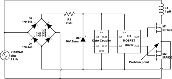
I am trying to create a circuit that will allow me to control the polarity of the current flowing through a coil in order to attract or repel a magnet. I would like to use two MOSFETs in series since activating a single MOSFET will half wave rectify the current by flowing through the body diode of the other MOSFET.

I have attached a simplified version of what I have envisioned. A microcontroller (not shown) would control through the Opto-coupler. The circuit works fine until the bottom MOSFET is activated. When that happens, on the negative AC power cycle the power flows through the bottom MOSFET, takes a least path of resistance shortcut at the problem point to the bridge rectifier and back to it's home in 110VAC. Poof.

In theory, a battery could operate this circuit fine, but my I would like to design this circuit so it works completely on AC power. How can I control these MOSFETS without shorting the circuit?
schematic

simulate this circuit – Schematic created using CircuitLab

\$\endgroup\$
3
  • \$\begingroup\$ Hmm...okay, I think I know what you're doing here. You're selectively half-wave rectifying the mains into your coil to produce the desired polarity, correct? Because you might be able to adapt a more traditional "light-dimmer" circuit to do that, as in my answer here: electronics.stackexchange.com/questions/148078/… However, you'll need to add a snubber (resistor+capacitor in series) across the power triac to try and prevent the false triggers as described in my notes over there. Did I read you correctly? \$\endgroup\$
    – AaronD
    Commented Apr 14, 2015 at 2:54
  • \$\begingroup\$ FYI: as I was designing my version for lighting, I went through a version very similar to yours and found the same problem...and a black streak on my bench! :-) \$\endgroup\$
    – AaronD
    Commented Apr 14, 2015 at 2:57
  • \$\begingroup\$ Can you use a relay to do the polarity reversal or must it all be semiconductors? \$\endgroup\$
    – EM Fields
    Commented Jun 10, 2015 at 16:42

3 Answers 3

1
\$\begingroup\$

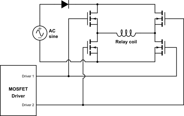
If you're okay using four MOSFETs instead of two, you could use a pair of push-pull circuits. Adding a diode in the AC path will prevent reverse conduction through the body diodes. If you want to draw current during both half-cycles, use a bridge rectifier. Or you could add a capacitor if you want something closer to DC.

schematic

simulate this circuit – Schematic created using CircuitLab
\$\endgroup\$
2
  • \$\begingroup\$ Adam, thanks for your suggested circuit. I did actually consider a circuit like this. However, it seems that there may be a problem in the Vgs. Somehow the MOSFET needs to share a reference with the driver in order to drive the VGS, but I'm not sure how this can be accomplished. \$\endgroup\$
    – jon
    Commented Apr 14, 2015 at 18:13
  • \$\begingroup\$ The driver would be referenced to the negative end of the AC line through D3, but I supposed that's not the best ground. Depending on how much current the relay takes, you might be able to drive it from the cathode of D1/2. You'll probably need something bigger than a 1N4148, though. The FETs can then use the anode of D3/4 as a ground, just like the opto-coupler and driver. \$\endgroup\$
    – Adam Haun
    Commented Apr 14, 2015 at 18:53
0
\$\begingroup\$

First, figure out the desired flow of the power. Draw the circuit in an H bridge configuration, where one side of the H bridge is D1 and D3, other side is M1 and M2. You'll see the L1 is not in the right place, the load should the load across the H bridge.

Next, find a few ways to control it. Usually this kind of solution needs an isolated power or isolated drivers, perhaps with optocouplers after your MOSFET driver, not just front of it.

Did you consider a TRIAC instead? You can have only the + or - half wave to drive your load, and you've only used one power component.

\$\endgroup\$
1
  • \$\begingroup\$ I have looked at similar TRIAC solutions, but I had been attracted to the MOSFET solution since I wanted unidirectional current and the TRIAC is bidirectional. I suppose I could put a TRIAC in series with a diode to make it unidirectional. If I did two of these TRIAC+diode combinations in a parallel path, with the diodes reversed on each path, this would let me control the direction of the current, right? Now that I think about it, maybe I should be looking at SCRs instead... \$\endgroup\$
    – jon
    Commented Apr 14, 2015 at 18:22
0
\$\begingroup\$

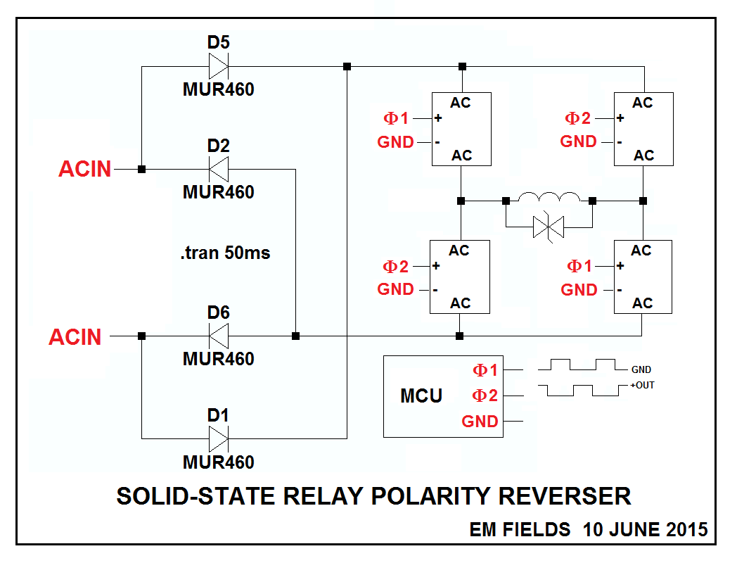
Here's an easy way to do it using solid-state relays, and here's an OPTO 22 selection guide, representative of what's generally available with DC control from all of the SSR guys.

enter image description here

\$\endgroup\$

Your Answer

By clicking “Post Your Answer”, you agree to our terms of service and acknowledge you have read our privacy policy.

Not the answer you're looking for? Browse other questions tagged or ask your own question.