3
\$\begingroup\$

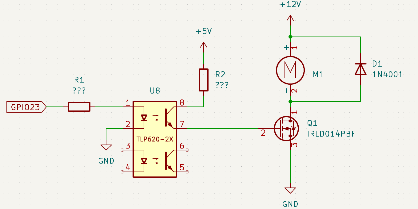
I am working on a project where I need to control this water pump using a Raspberry Pi 3B+.

Currently, I've chosen the IRLD014PBF N-channel MOSFET to drive this water pump. For added protection to my RPi GPIO, I've decided to incorporate the TLP620-2X opto-coupler into the circuit.

RPi MOSFET water pump circuit

I have attached the schematic for review and would appreciate feedback on the component selection. Specifically, I am unsure about the chosen MOSFET and opto-coupler, and the necessity of resistors R1 and R2 (would like to know if they are required, as well as recommendations for their values).

\$\endgroup\$
1
  • \$\begingroup\$ Add a resistor between the gate and ground (1k Ohm). \$\endgroup\$
    – Antonio51
    Commented Nov 11, 2023 at 10:37

1 Answer 1

3
\$\begingroup\$

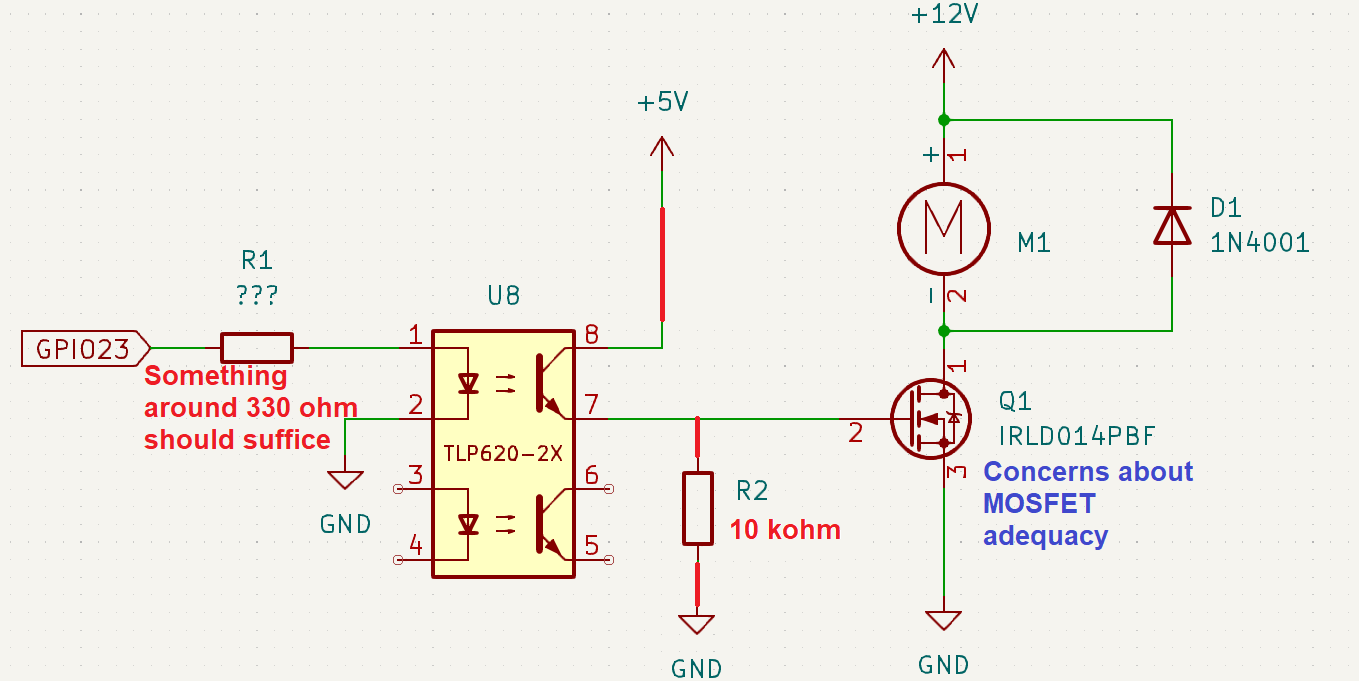
You should consider using this modified circuit: -

enter image description here

Regarding the MOSFET (rated at just over 1 amps continuous), it's unclear what current the pump takes despite reading the data sheet. I suspect that the MOSFET may overheat if you don't choose something with a little more capability.

OK, I've re-read the data sheet and, it seems to imply the pump takes between 65 mA and 500 mA. However, if the pump got blocked (quite a common thing) then the current may exceed the rating for the MOSFET.

\$\endgroup\$
5
  • \$\begingroup\$ Thank you for the modified circuit! Regarding the water pump, I may be implementing an additional circuit for current sensing, to prevent the current from exceeding the MOSFET's ratings. As for the need for a heatsink on the MOSFET, I've completed the following calculations: with a current consumption of 750mA and an Rds of 0.2 ohms, the power dissipation is 0.1125 W. Given the MOSFET's thermal resistance of 120°C/W, the temperature is expected to rise by approximately 13.5°C. Do you think it would be adequate to operate without a heatsink? \$\endgroup\$ Commented Nov 11, 2023 at 10:48
  • \$\begingroup\$ @Engineering007 I personally think you are pushing it too hard and that a MOSFET with lower on resistance would be a more reliable choice (maybe 0.1 ohms with a Vgs of 5 volts). It's just a little too close to the "unreliable" area to make me convinced. \$\endgroup\$
    – Andy aka
    Commented Nov 11, 2023 at 10:57
  • \$\begingroup\$ Regarding the heatsink, because the localized temperature around the MOSFET rises (due to power dissipation) you ought to factor that in. I mean, I don't know what external ambient temperature you are expecting or, how the MOSFET is enclosed to make a judgement call on this. \$\endgroup\$
    – Andy aka
    Commented Nov 11, 2023 at 10:59
  • \$\begingroup\$ Agreed, the initial MOSFET choice was somewhat optimistic. Based on your advice, I've opted for the IRLD024PBF, featuring an Rds of 0.1 ohms @ 5V and a higher continuous rating of 2.5A (up from 1.7A). This MOSFET dissipates about 56mW @ 750mA, resulting in a ΔT of 6.75 °C. Regarding the electronic enclosure, intended for an RC submarine, it's completely sealed without airflow, yet the surrounding water may provide a cooling effect. \$\endgroup\$ Commented Nov 11, 2023 at 11:51
  • \$\begingroup\$ I feel more comfortable about that choice but, for a sub maybe you should have an internal temperature monitor that shuts down stuff should it rise too high. I guess if it's a metal body it'll be alright. \$\endgroup\$
    – Andy aka
    Commented Nov 11, 2023 at 11:54

Your Answer

By clicking “Post Your Answer”, you agree to our terms of service and acknowledge you have read our privacy policy.

Not the answer you're looking for? Browse other questions tagged or ask your own question.