8
\$\begingroup\$

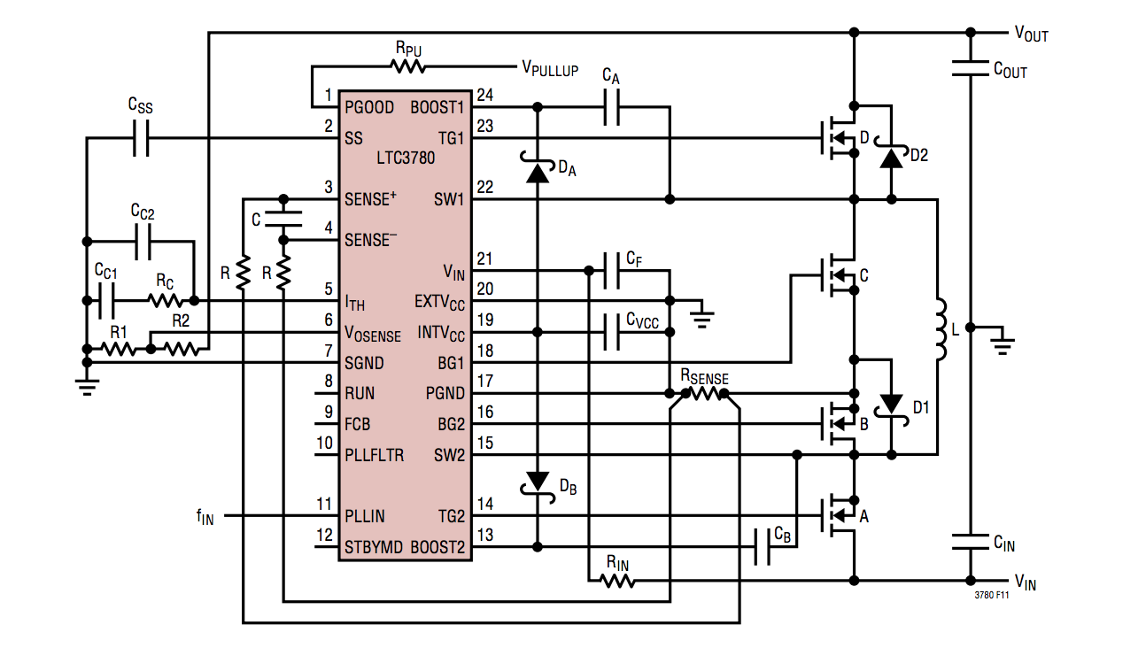
I'm reading about buck-boost DC-DC converters lately and one thing is still not very clear for me. Most of the converter ICs that I've seen have a feedback loop input pin. For example LTC3780 requires a voltage divider, on the typical application it's created with R1 and R2 resistors (on the left):

enter image description here

As far as I know the only way to adjust such a circuit from a microcontroller is to use a digital potentiometer. The problem is, digital potentiometers that I found are either quite expensive or have a huge tolerance, like 20 or 30%.

Is there any better way to adjust the output voltage of such converters? And if not, are there any other types of ICs that allow easier control from a microcontroller?

\$\endgroup\$
10
  • \$\begingroup\$ is it enough to adjust the fb network? don't you also need to change the caps and inductor to match (outside of a certain range)? \$\endgroup\$
    – kolosy
    Commented Apr 28, 2015 at 18:48
  • \$\begingroup\$ Are you looking for a wide voltage range? There are digital set regulators that you can set over i2c. There are also pmics power management ics that you can use to margin voltages and look at current and voltage \$\endgroup\$ Commented Apr 28, 2015 at 19:30
  • \$\begingroup\$ You could also consider designing your own around a microcontroller and skip the IC entirely. \$\endgroup\$
    – pjc50
    Commented Apr 28, 2015 at 19:56
  • \$\begingroup\$ is it possible to isolate the feedback stage with a high speed buffer, followed by a summing or difference amp to allow a MCU with a DAC or GPIO based R2R ladder to apply an offset/adjustment to the feedback network voltage, to adjust the output voltage digitally (despite there being an analog interface) \$\endgroup\$
    – KyranF
    Commented Apr 28, 2015 at 20:19
  • \$\begingroup\$ R2 and R1 form the feedback divider for the VOSENSE pin, you would basically take that node and do what I was saying before, by inserting some analog circuitry to allow a digital offset by way of a DAC \$\endgroup\$
    – KyranF
    Commented Apr 28, 2015 at 20:20

2 Answers 2

7
\$\begingroup\$

Although the absolute value of a digital potentiometer's resistance may vary 30%, the matching between the internal resistors is really good. This means that for a voltage divider (to wit, a potentiometer), the voltage division accuracy is quite good, since the voltage division factor relies entirely on the ratio of the resistors used, not their absolute value.

If your output voltage is less than the digital potentiometer's maximum voltage rating, you can simply use a digital potentiometer to stand in for the feedback network without any fanfare. Most digital pots can take only 5.5V, but some are rated for substantially more.

If your output voltage is higher than the digital potentiometer's maximum rating, or if you want fine adjustment, you can combine the digital potentiometer with external resistors to form a compound voltage divider. Note that this will cause the digital potentiometer's absolute value variation to come into play. Techniques exist to minimize this error, as covered here.

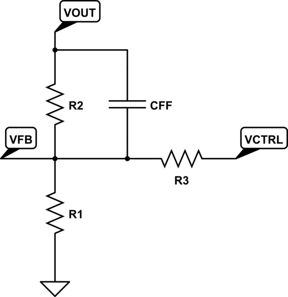
If you want to avoid digital potentiometers altogether, you can make the feedback divider take input from a D/A as well, as shown here by having a D/A drive \$V_{CTRL}\$:
schematic

simulate this circuit – Schematic created using CircuitLab

Since the feedback voltage \$V_{FB}\$ will be regulated by the LTC3780 to 0.8V, the output voltage will be regulated to:

$$V_O=\left(1+\frac{R_2}{R_1}\right)0.8-\frac{R_2}{R_3}(V_{CTRL}-0.8)$$

Setting \$V_{CTRL}\$ to 0.8V causes no change in the output voltage; increasing \$V_{CTRL}\$ causes the output to drop, and decreasing \$V_{CTRL}\$ causes it to rise.

It should be noted that no matter what you do, you should carefully evaluate the regulator and adjust components (\$L\$, \$C_{OUT}\$, \$I_{TH}\$ network) to ensure stability over all operating conditions. When in doubt, lean to the conservative side here.
\$\endgroup\$
8
  • \$\begingroup\$ this is a very informative answer, thanks! in last option, what's the role of CFF? is it for stabilizing output? And if yes, what value should I choose, I suppose something small like 470n with a fairly small R3? \$\endgroup\$ Commented Apr 29, 2015 at 9:28
  • 1
    \$\begingroup\$ @PiotrSarnacki, \$C_{FF}\$ is a feed-forward capacitor. You might pick a value of, say, 1nF. The presence of \$R_3\$ reduces the loop gain, so you may want \$C_{FF}\$ to keep the loop gain invariant to the feedback divider ratio. That said, you also might not want it. As mentioned, you'll want to carefully evaluate the regulator stability... and component selection could be a lengthy question (and answer) of its own. So... you could leave \$C_{FF}\$ non-populated, and add it only if you determine it's needed. \$\endgroup\$
    – Zulu
    Commented Apr 29, 2015 at 16:39
  • \$\begingroup\$ I was playing with the circuit from the last option in LTSpice and either I really don't understand it or I do something wrong. The problem is that as far as I understand the datasheet, Vosense is an input pin. Vout voltage is steered by the buck/boost circuit on the right (MOSFETs etc) and then Vosense reads the output voltage divided by the voltage divider and adjusts MOSFETs duty cycles accordingly. It seems that on your circuit Vout would be connected to Vout, Vfb to Vosense and Vctrl to the uC. If that's true I fail to see how would that work with setting proper voltage on Vosense. \$\endgroup\$ Commented Apr 30, 2015 at 12:15
  • 1
    \$\begingroup\$ @PiotrSarnacki, you are correct: \$V_{OUT}\$ connects to \$V_{OUT}\$, \$V_{FB}\$ connects to \$V_{OSENSE}\$, and \$V_{CTRL}\$ connects to a D/A converter from the μC. And as described, the output voltage will be \$V_{OUT}=\left(1+\frac{R_2}{R_1}\right)0.8-\frac{R_2}{R_3}(V_{CTRL}-0.8)\$. "If that's true I fail to see how would that work with setting proper voltage on Vosense." What do you mean? \$\endgroup\$
    – Zulu
    Commented Apr 30, 2015 at 16:53
  • 1
    \$\begingroup\$ @PiotrSarnacki, even though \$V_{OSENSE}\$ is an input, it is "servoed" to 0.8V. You can think of the buck-boost converter as a giant power op-amp, with an [internal] 0.8V reference connected to its [internal] non-inverting input. The output of the converter (\$V_{OUT}\$) will be driven to whatever is needed to make its inverting input (\$V_{OSENSE}\$) to equal its non-inverting input, which is 0.8V. This is the basic idea of all control systems. So when doing calculations, you can simply assume that, once the converter has reached steady-state, \$V_{OSENSE}\$ will be 0.8V. \$\endgroup\$
    – Zulu
    Commented Apr 30, 2015 at 23:06
1
\$\begingroup\$

The easiest way is with a digital pot, just use it in ratiometric mode, i.e. as a potentiometer, not a rheostat. When used as a potentiometer the gross resistance tolerance applies to both sections of the part, and so doesn't matter. A 6-bit pot should be able to have less than 0.5 lsb error, even though the resistance tolerance might be 20%, and should cost less than ~$1 (in the US anyway).

Alternatives like adding amplifiers to adjust the reference via DAC control are doable, but much more complicated. You would probably have to add 2 OpAmps to get the proper adjustment and polarity.

\$\endgroup\$

Your Answer

By clicking “Post Your Answer”, you agree to our terms of service and acknowledge you have read our privacy policy.

Not the answer you're looking for? Browse other questions tagged or ask your own question.