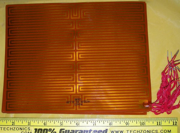
You can even make a long spiral of a thin trace in a few places and use those as thermal sensors. It'll require a bit of experimentation, but it can work very well to build a temperature controlled board like that. The thermal drift in resistance in copper is only 3.9*10^-3, so if you can make a 10 ohm trace at 20 degrees C, it'll be about 12.3 ohm at 80 degrees C. Certainly a detectable difference, but not the easiest.
(you could use the calculator at the bottom of this page)
You can also just put a few PTC or NTC modules on one of the surfaces :-) But that's less impressive/magic :-P
As @PlasmaHH suggests in a comment you should take care not to start out pumping energy into it, to prevent from large differentials from occurring. If you add low to medium amounts of energy to the middle layer that energy can have time to dissipate evenly.
You can help the dissipation of the energy by leaving copper in between the heating traces that can carry away excess heat from one spot without components to a spot with many. You can help it even more by putting the heating between two nearly solid power planes, but I don't expect that to be needed. The thermal conductivity of FR4 materials is already very decent as well.
Just don't take away any copper that you don't need for heating, that'll help a lot, and if you can connect those to a safe ground trace or plane: First of all that will conduct the heat away to that plane, which helps, but it also avoids resonances and such when you start PWM-ing the heater.

