11
\$\begingroup\$

The app notes I've seen for a SEPIC converter1 all tell me to size the coupling capacitor for ripple currents and voltages. I haven't seen one that tells me how to size the capacitance. Obviously there's some minimum; zero capacitance means no coupling, so the input has no effect on the output. To make the switching effects couple from input to output, we need enough capacitance to overwhelm any parasitic capacitances on the output side of the converter. Maybe 1000 pF should do that, I think, depending on what else is going on in the circuit. But the reference design I've inherited uses a 1 uF cap, which seems like it may be overkill for that purpose. Which makes me think there's more going on for sizing that capacitor than just overcoming parasitic capacitance.

How do I properly size the coupling capacitor in a SEPIC converter?

1 For example, this Texas Instruments AN-1484 Designing A SEPIC Converter.

\$\endgroup\$
10
  • \$\begingroup\$ Which converter? \$\endgroup\$ Commented Oct 12, 2015 at 13:37
  • 1
    \$\begingroup\$ When I did a SEPIC design I calculated the complex reactance 1/(2*pi*fs*C) and set it so that the reactance would be much less than my smallest load resistance. It worked fine. \$\endgroup\$ Commented Oct 12, 2015 at 13:45
  • \$\begingroup\$ Let's assume a certain properly designed SEPIC converter which has a coupling cap of x Farad. Now I want a similar converter to deliver a 10 times higher current. Then I would just scale everything relevant to that 10 times current up by a factor of 10 so now I would need a capacitor of value 10 times x. See you cannot say 1000pF should do or 1uF is overkill. It all depends on the design. \$\endgroup\$ Commented Oct 12, 2015 at 13:48
  • \$\begingroup\$ I'm not sure why the downvote or close vote. Some constructive criticism, please? \$\endgroup\$ Commented Oct 12, 2015 at 13:51
  • \$\begingroup\$ @LeonHeller Which converter? A SEPIC converter. en.wikipedia.org/wiki/Single-ended_primary-inductor_converter Did you mean something else? \$\endgroup\$ Commented Oct 12, 2015 at 13:52

2 Answers 2

6
\$\begingroup\$

To make the switching effects couple from input to output, we need enough capacitance to overwhelm any parasitic capacitances on the output side of the converter.

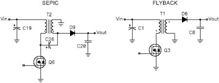
If the two inductors are coupled then a SEPIC can become a flyback converter and the capacitor is not needed. This tells you that there is no minimum value for the coupling capacitor: -

enter image description here

I think it's worth linking to this article where I stole the picture.

The article is a called "Power supply topology: SEPIC vs Flyback" published by Electronics Weekly.

Basically and in simple terms you don't need the capacitor if using coupled inductors but, the more capacitance you apply the more like a SEPIC converter it becomes with the various trade-offs you'll get.

\$\endgroup\$
13
  • \$\begingroup\$ Good answer. But what if the inductors aren't coupled? \$\endgroup\$ Commented Oct 12, 2015 at 14:31
  • 2
    \$\begingroup\$ If you are using uncoupled inductors then all the energy reaching the load has to pass thru the capacitor and although efficiency doesn't significantly drop with a lower value capacitor the Vin range that can sustain the output voltage does. So I would consider Xc should be one-tenth (or lower) than Rload (min). I liken that capacitor to the one that "loses" voltage in one of those transformerless power supplies that keep cropping up every now and then. \$\endgroup\$
    – Andy aka
    Commented Oct 12, 2015 at 14:40
  • 1
    \$\begingroup\$ FWIW (moot) I've seen a SEPIC 'expert' rail on about a coupled inductor implementation NOT being a SEPIC. (And another offering a coupled version :-) ). \$\endgroup\$
    – Russell McMahon
    Commented Oct 14, 2015 at 0:24
  • 1
    \$\begingroup\$ Ask yourself, does the sepic store energy in the primary that is converted to energy in the secondary? If the answer is yes, then some designs will require an air gap to make maximum use of energy storage whilst minimising core saturation (energy wastage). \$\endgroup\$
    – Andy aka
    Commented Jan 6, 2019 at 10:40
  • 1
    \$\begingroup\$ I’m going round in circles here. If you have a specific question about capacitor types used in a sepic then maybe raise a new question. For the few instances I’ve designed a sepic, I’ve probably used an X7R and not had problems. \$\endgroup\$
    – Andy aka
    Commented Jan 6, 2019 at 10:47
4
\$\begingroup\$

Most of the steady state equations for a CCM SEPIC rely on voltage across \$C_c\$ being ~\$V_{\text{in}}\$, so it's best to keep the ripple voltage small compared to \$V_{\text{in}}\$. When using an electrolytic capacitor, choosing a part that could take the RMS current, pretty much makes ripple voltage across \$C_c\$ small enough. Of course, this may not be true with a ceramic part.

For parts with low ESR, maximum ripple voltage across \$C_c\$ would be less than \$\frac{I_{\text{out}}}{C_c f_{\text{pwm}}}\$. Start with 0.1 \$V_{\text{in}}\$ ripple voltage to choose a value for \$C_c\$. Here's a basic reference for designing a SEPIC, although it doesn't explicitly tell you how to choose the value of \$C_c\$.

It's interesting how, if \$C_c\$ is made small value and the output inductor is made smaller than the input inductor, and maybe a little capacitance is added across the switch, the SEPIC starts to look like a Class E converter.

\$\endgroup\$
1
  • \$\begingroup\$ Which would you recommend on a basic SEPIC. Because can't it be dangerous to put a ceramic as decoupling (X7R) because of its low ESR and therefor have an unstable circuit? \$\endgroup\$
    – J. Joly
    Commented Jan 6, 2019 at 8:56

Your Answer

By clicking “Post Your Answer”, you agree to our terms of service and acknowledge you have read our privacy policy.

Not the answer you're looking for? Browse other questions tagged or ask your own question.