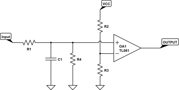
You can use a RC circuit followed by a comparator.

simulate this circuit – Schematic created using CircuitLab
R2 and R3 form a voltage divider and create a reference for the comparator. The voltage at this reference point is
$$V_{ref} = V_{cc} * \frac{R3}{R2 + R3}$$
When the input to the non inverting (+) terminal of the comparator is less than the reference, the output signal will be low. As soon as the input to the + terminal goes above the reference, the output signal will be high.
R1 and C1 form a traditional RC circuit. The voltage on the capacitor Vc is given by
$$V_c = V_{cc}(1 - e^{\frac{-t}{RC}})$$
To compute the required values for R and C, we set the voltage across the capacitor to be equal to our reference voltage.
$$V_{ref} = V_{c}$$
$$V_{cc} * \frac{R3}{R2 + R3} = V_{cc}(1 - e^{\frac{-t}{RC}})$$
Where we set t equal to our required delay in seconds. We then either choose a fixed value for R or a fixed value for C and solve the equation for the desired unknown.
As an example, let $$R1 = R2$$ so that $$V_{ref} = 0.5V_{cc}$$ We then have $$1 - e^{\frac{-t}{RC}} = 0.5$$
Lets fix t to be 1 second $$1 - e^{\frac{-1}{RC}} = 0.5$$ $$e^{\frac{-1}{RC}} = 0.5$$ $$RC = 1.44$$ We can then either fix a value for R or fix a value for C and compute the unknown. Lets fix R = 1k then $$C = \frac{1.44}{1000}$$ $$C = 1.44mF$$
R4 is optional but it is there to provide a path for the capacitor to discharge after being charged. You can calculate the value of R by determining how quickly you want the voltage to drop.
Also note that the charging of C1 through R1 may load down your input signal. If the input signal is a high impedance signal, consider adding a buffer between the input and R1. This will allow R1 to charge C1 as expected.

