0
\$\begingroup\$

How do I build a circuit that gives out a "high" only when given in a "high" continuously for a preset time period? The input is actually the out from a logic gate.

The following details have been added considering the suggestions from Andy Aka. The rate at which the output goes from high to low once the input is low, need not be fast and a delay up to a few seconds is tolerable. Also if the input is not high long enough to set the output high, the timer should be reset, which could also be non-spontaneous and could take up to a few seconds.

\$\endgroup\$
14
  • \$\begingroup\$ How quickly should the output revert to low when the input goes low? Note that the answer you have accepted may not achieve what you want once you have thought about this. Also, during the high being present, but the output not yet gone high, should the occasion of a low reset this time period thus forcing the time period to start over again once the high returns? Think about what you are asking. \$\endgroup\$
    – Andy aka
    Commented Jul 13, 2016 at 7:17
  • \$\begingroup\$ @Andyaka One thing I missed in my details is that the input is actually the out of a logic gate and hence all the issues that you have mentioned are absent. The out goes low as soon as the in goes low. In the occasion of a low before the output goes high, the timer is reset and that's how I want it to be. This circuit is for responding to only a clear, clean signal originating from an environment with lots of noise. Guess I should have added that in the details. \$\endgroup\$ Commented Jul 13, 2016 at 7:27
  • \$\begingroup\$ How can the circuit in the answer you accepted fulfill what you have just told me. How can its output go low as soon as the input goes low. How can the charging of the capacitor reset when input goes low briefly? Please explain how the circuit you have accepted meets with your requirements. \$\endgroup\$
    – Andy aka
    Commented Jul 13, 2016 at 7:33
  • \$\begingroup\$ @Andyaka The circuit in the answer I accepted doesn't work the way I want it to with the discharging resistor R4 and if the input is either high or nothing. But as my input is either high or low, the discharging resistor can be omitted since the low from the input neutralizes the positive charge on the capacitor plate to which it is connected, almost instantly. I had tried out the circuit first and I accepted it because it suited my need. \$\endgroup\$ Commented Jul 13, 2016 at 7:39
  • 1
    \$\begingroup\$ @Andyaka I am not deleting anything. I needed help, I asked for it and I got it. I didn't add a lot of details into the question since it didn't matter to me much. I've tried my best to fix this for the "posterity" and I am done. \$\endgroup\$ Commented Jul 13, 2016 at 9:44

1 Answer 1

1
\$\begingroup\$

You can use a RC circuit followed by a comparator.
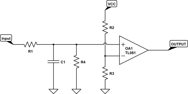
schematic

simulate this circuit – Schematic created using CircuitLab

R2 and R3 form a voltage divider and create a reference for the comparator. The voltage at this reference point is

$$V_{ref} = V_{cc} * \frac{R3}{R2 + R3}$$

When the input to the non inverting (+) terminal of the comparator is less than the reference, the output signal will be low. As soon as the input to the + terminal goes above the reference, the output signal will be high.

R1 and C1 form a traditional RC circuit. The voltage on the capacitor Vc is given by $$V_c = V_{cc}(1 - e^{\frac{-t}{RC}})$$

To compute the required values for R and C, we set the voltage across the capacitor to be equal to our reference voltage.

$$V_{ref} = V_{c}$$ $$V_{cc} * \frac{R3}{R2 + R3} = V_{cc}(1 - e^{\frac{-t}{RC}})$$

Where we set t equal to our required delay in seconds. We then either choose a fixed value for R or a fixed value for C and solve the equation for the desired unknown.

As an example, let $$R1 = R2$$ so that $$V_{ref} = 0.5V_{cc}$$ We then have $$1 - e^{\frac{-t}{RC}} = 0.5$$

Lets fix t to be 1 second $$1 - e^{\frac{-1}{RC}} = 0.5$$ $$e^{\frac{-1}{RC}} = 0.5$$ $$RC = 1.44$$ We can then either fix a value for R or fix a value for C and compute the unknown. Lets fix R = 1k then $$C = \frac{1.44}{1000}$$ $$C = 1.44mF$$

R4 is optional but it is there to provide a path for the capacitor to discharge after being charged. You can calculate the value of R by determining how quickly you want the voltage to drop.

Also note that the charging of C1 through R1 may load down your input signal. If the input signal is a high impedance signal, consider adding a buffer between the input and R1. This will allow R1 to charge C1 as expected.

\$\endgroup\$
2
  • \$\begingroup\$ Should the "delay" be reset if while the positive voltage is applied, it returns to 0V for a short period? The OP indicates it should despite accepting this answer. \$\endgroup\$
    – Andy aka
    Commented Jul 13, 2016 at 9:04
  • \$\begingroup\$ This circuit is acceptable with a minor tweak. Ditch the discharging capacitor as the logic out will take care of that (as it is it's optional). It is fine for a quick and dirty solution as it depends on the exponential charging and discharging of a capacitor which could bring in delays where you might not want it. \$\endgroup\$ Commented Jul 13, 2016 at 9:17

Not the answer you're looking for? Browse other questions tagged or ask your own question.