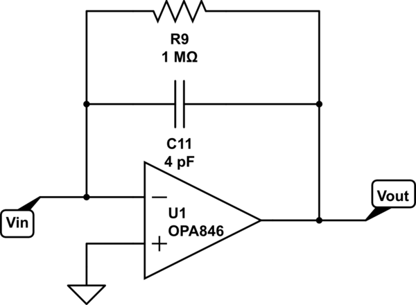
I've inherited an charge amplifier/shaping circuit from my predecessor. When he wanted to make a low-pass filter with current-to-voltage conversion, he had a standard circuit like:

simulate this circuit – Schematic created using CircuitLab
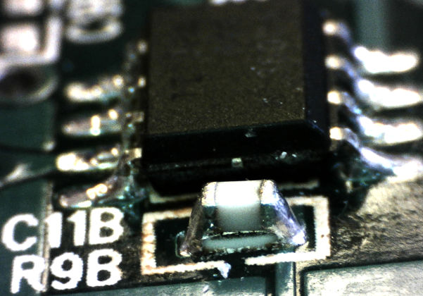
He would make a single footprint for R9 and C11 and solder them on top of each other like this:
What reasons could he have had for designing the circuit this way? I have not seen this particular technique anywhere else. To my eye, it looks problematic, both from an assembly point of view as well as for minimizing the capacitor's feedback path. For what it is worth, the circuit is meant to deal with extremely short (~4ns) pulses.
Edit: Thanks for the insightful comments! The idea behind this circuit is, indeed to widen the pulses generated by, in this case, a PIN Diode. The capacitor is COG +/-10%.
To expand on my confusion regarding this circuit, I agree that parasitics are changed by stacking. But I should have mentioned that the capacitor and resistor are both 0603 (if it wasn't clear from the picture). I'd have thought that if the designer were concerned about parasitics, his first step would have been to reduce the component size.
I'm correcting some other issues with the board and wanted to make sure I wasn't missing something critical in this stacking business. Thanks again for the useful insight.

