1
\$\begingroup\$

I am attempting to rejig a brushless DC motor to work as a dynamo - I am unsatisfied with the paltry 3W output max of my most powerful hand-crank dynamo and am trying to see if I can get something with a little more power by using a larger rotor and gears, ideally more than about 10W.

I have salvaged this from an old floppy drive: Old floppy drive BLDC motor
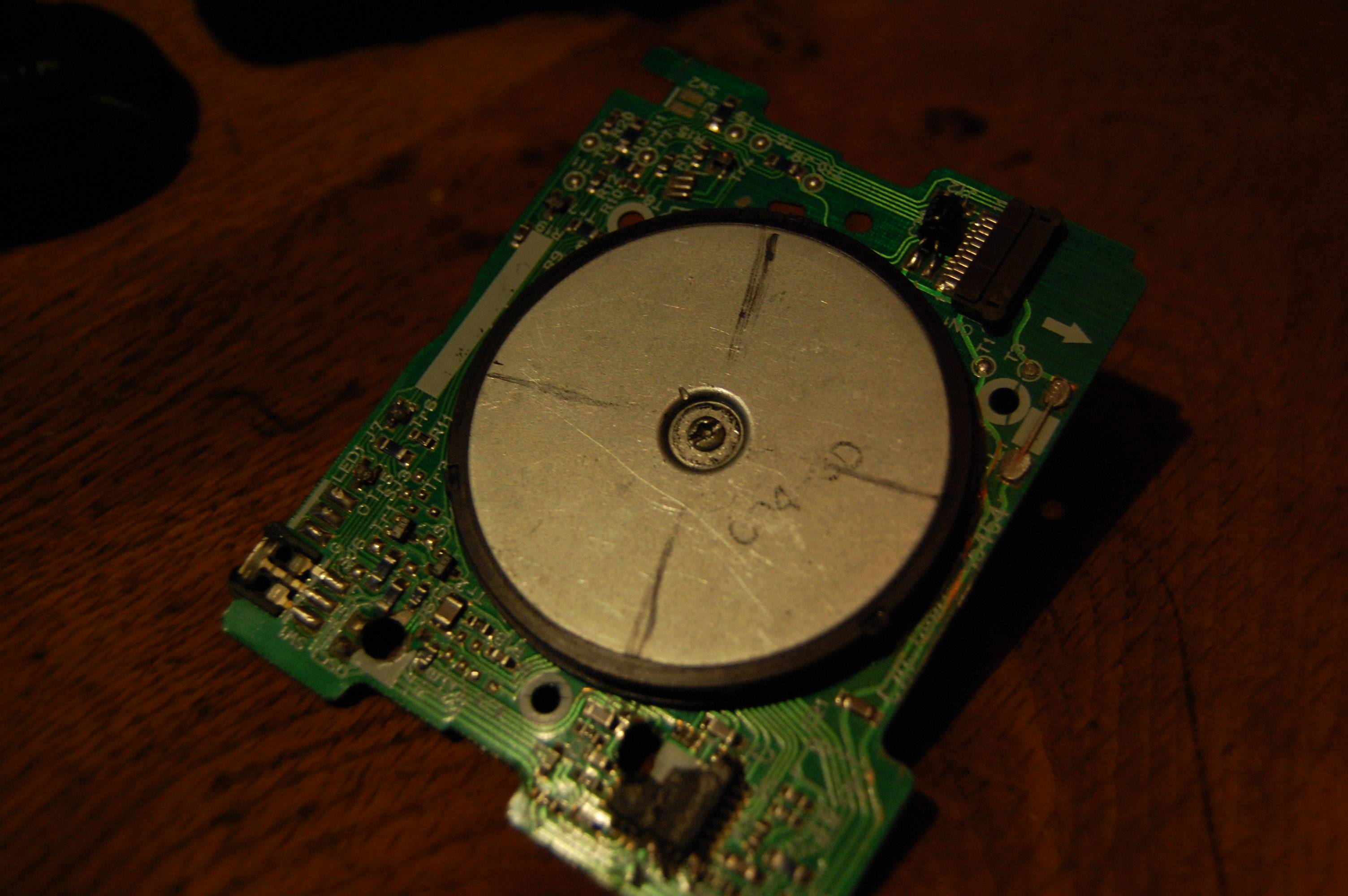
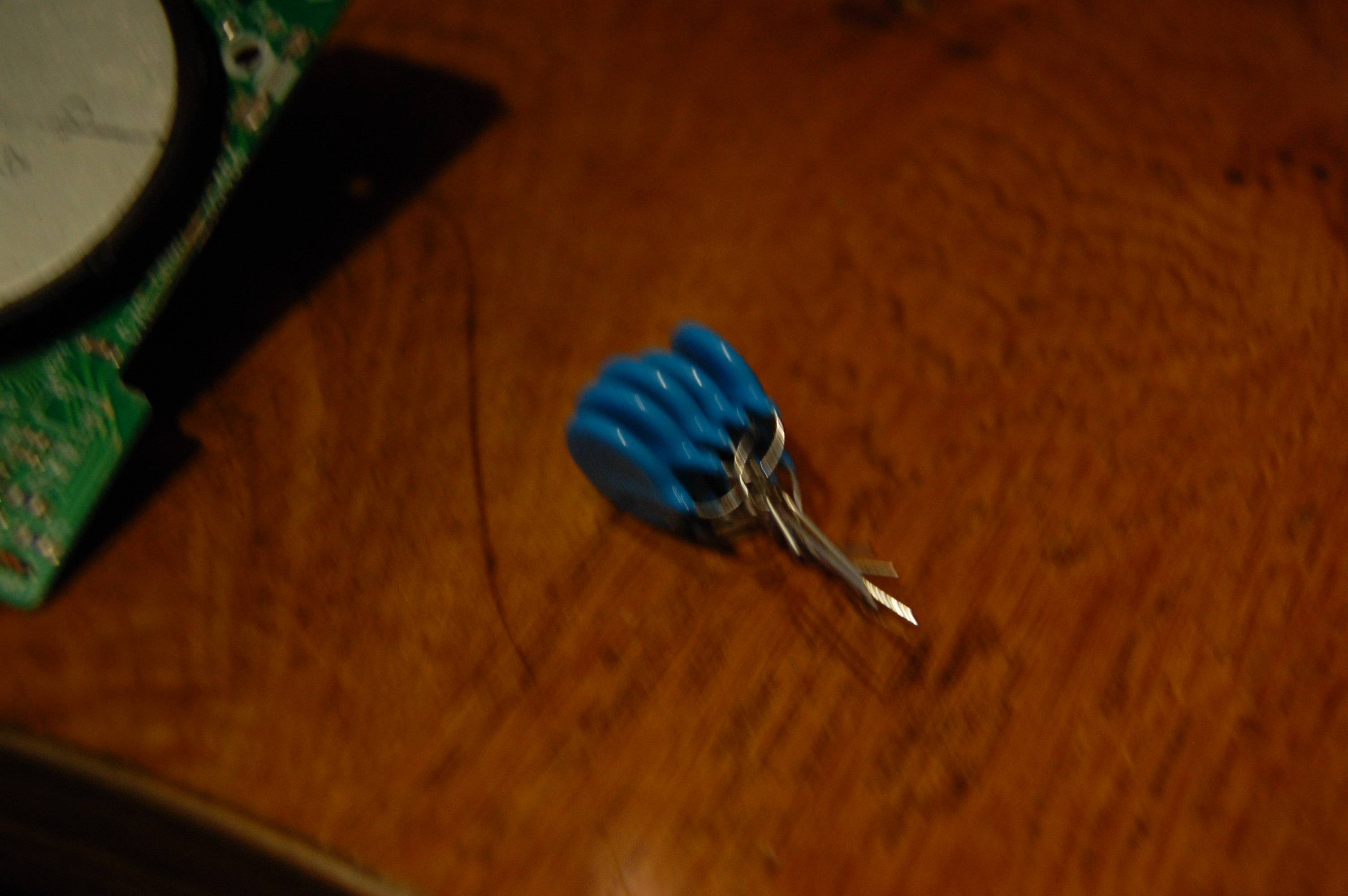
I attempted to figure out the number and position of poles yesterday on the rotor. Unfortunately, thanks to my impatience I used a neodymium magnet to do this, which has significantly decreased the rotor's field strength. As a rough indication, the maximum open circuit voltage i could get by spinning the rotor with my finger was around 1.5V, whereas now it is just under 0.5V. I would like to be able to remagnetize the rotor if I can. Some research has led me to How to re-magnetize a permenent magnet motor of small size (model railroad)? which answers my question qualitatively, if not quantitatively - namely, passing a pulse of sufficient current for a short period of time through a coil can remagnetize any adjacent magnets. I have made a small capacitor bank, 5x 100uF:

enter image description here

which is charged up to 30V (the max my power supply outputs). I haven't yet added the diodes for preventing ringing and freewheeling. Given each coil has a DC resistance of ~1.7ohms, this should give a max current of about 17A, assuming I can minimize resistance. Would this be enough to have any appreciable effect on the magnetization? If not, is there any way to get sufficient magnetization back or is this a lost cause?

\$\endgroup\$
7
  • \$\begingroup\$ I don't believe that magnetic ring presents a strong field. It's not designed for efficient conversion, even before you may have damaged it. Shouldn't you consider using the strongest neodymium magnets you can afford to apply? \$\endgroup\$
    – jonk
    Commented Aug 6, 2016 at 21:15
  • \$\begingroup\$ Right, but the question is: will I be able to make a strong enough rig that's close enough to the coils? Is this possible without industrial equipment? \$\endgroup\$ Commented Aug 6, 2016 at 21:30
  • \$\begingroup\$ If you really want to do the best with a generator, then I think you will use N50 neodymium magnets and avoid weak magnets. (If I remember, those PC board ring motor magnets have dozens if not more poles to them and they are weak, besides. You can dig your fingernail into them, too. They are cheap and serve a need. That's all.) Look at: instructables.com/id/DIY-1000-watt-wind-turbine as an idea you might learn from. (I only know I would NOT use the magnetic ring you are considering.) \$\endgroup\$
    – jonk
    Commented Aug 6, 2016 at 21:33
  • \$\begingroup\$ That's some good information! I'll have to give that a try. \$\endgroup\$ Commented Aug 6, 2016 at 22:23
  • 1
    \$\begingroup\$ those are not 100uF caps, those are 100nF. \$\endgroup\$
    – Neil_UK
    Commented Aug 7, 2016 at 5:27

1 Answer 1

1
\$\begingroup\$

There may be a helpful and useful "instructables" article for you to consider: DIY instructable on making a wind-powered generator. There's also a PDF on making permanent magnet alternators that may be of some help, as well. If all you want to do is to generate on the order of 10W, then the above designs will have to be scaled down. (I'm also somewhat interested in the topic, so I may attempt something like this over the next year.)

The second link above emphasizes my point about using neodymium magnets, saying that these are what makes such a DIY generator within reach of a hobbyist. So it does support my earlier suggestion regarding the type of permanent magnet you should consider using.

For smaller alternators, such as the one you may be considering, the use of the commonly found smaller cylindrical shaped magnets are fine. You should look for the more powerful kinds, such as the N50 type. The higher the number, the stronger. (I think N50 is near the top of affordable magnets and is commonly found on ebay and elsewhere.) These cylindrical magnets are configured (usually) so that one circular face is (N)orth and the other circular face is (S)outh.

The magnets are used to complete two rotors, in between which is sandwiched a stator (a collection of coils laid out and wired up in a particular way.) The stator stays still and is connected to circuitry. The paired rotors within which the stator is sandwiched, rotate with the applied mechanical rotation mechanism (hand crank, etc.) The stator material holding the coils should not interfere with the magnetic fields, so a resin of some kind is often used for this, letting it harden with the coils embedded in it. The rotors are usually a circular plate of iron or steel (necessary) and you will want to place the cylindrical magnets so that they alternate the polarity of the face against the plate as they are added evenly around the rotor plate. (An even number of them.) The steel or iron in the plate forms an easy pathway for the magnetic flux. The magnets around the rotor will then have only one exposed face to rotate near the coils in the stator.

A common DIY arrangement makes the stator diameter larger than the rotor diameter, so that the outside perimeter of the stator can be bolted to a fixed block. The stator has a hole in the center so that an axle may connect the two rotors on either side and spin freely. The inner faces of the rotors and both faces of the stator need to be very flat and arranged as close to each other as practical. Shoot for \$\frac{3}{32}\$" but it's probably asking too much to get closer than \$\frac{1}{16}\$".

Complete details would be hard to include here in a long-term stable form, but here's another page where you can see how things might be assembled together: alternator assembly.

You will also need to find or design a controller for your purposes. But I'd recommend concentrating on completing a working alternator first and then purchasing the controller for your first attempt.

Best wishes!

\$\endgroup\$
4
  • \$\begingroup\$ Link-only answers is frowned upon here, please add the necessary information to the actual answer. \$\endgroup\$
    – pipe
    Commented Aug 6, 2016 at 22:45
  • \$\begingroup\$ @pip: Thanks. So are you thinking about me doing research on some specific neodymium magnets, their field intensities at distances, and forming some quantitative magnetic field and non-Coulumb electric field calculations here? Or just deleting the answer. If the first, I've got too much else to do. If the latter, that's fine. Mostly curious, as I'm only still struggling to understand what's fine and not fine here. Or did you mean something else? \$\endgroup\$
    – jonk
    Commented Aug 6, 2016 at 22:48
  • \$\begingroup\$ The only question to ask is: "Does this post answer the question even if the link is dead?". In this case it obviously doesn't, and the link is dead to me. I think it's using some crazy ad-enforcing javascript based redirection. If the link contains answers, you can summarize them - you don't have to do the actual research. \$\endgroup\$
    – pipe
    Commented Aug 6, 2016 at 22:51
  • 1
    \$\begingroup\$ @pipe: Thanks. That's clearer to me, now. I'll see about adding the extra effort, as you indicate I should (and your comment makes good sense to me now.) I'm out to chop wood for a bit, then back in. Will try and get it done soon. \$\endgroup\$
    – jonk
    Commented Aug 6, 2016 at 22:56

Your Answer

By clicking “Post Your Answer”, you agree to our terms of service and acknowledge you have read our privacy policy.

Not the answer you're looking for? Browse other questions tagged or ask your own question.