How can you determine BLDC motor rotation direction as logic high/low by reading hall switches? Not using an MCU, just analog/digital/logic ICs.
-
\$\begingroup\$ When you say "hall switches" do you mean "hall effect sensors used to switch the commutation on a brushless DC motor"? If so, then it's the order that switches are turn on/off. \$\endgroup\$– PuffafishCommented Sep 2, 2016 at 14:31
-
\$\begingroup\$ You will need a state machine, hopefully a digital one though some crude hacks with analog delays might work if you only care about a narrow range of speed. This is near the territory where the effort of avoiding an MCU just isn't effective unless the volume will be huge or you are doing it as an intellectual exercise - even the IC's you'd probably end up using will be larger than the applicable MCUs. \$\endgroup\$– Chris StrattonCommented Sep 2, 2016 at 14:34
-
\$\begingroup\$ @ChrisStratton: In the general case, you are correct. However if the signals from the Hall sensors overlap (like in a quadrature encoder), then a simple DFF is all you need to distinguish direction. \$\endgroup\$– Dave TweedCommented Sep 2, 2016 at 14:43
-
\$\begingroup\$ @Puffafish yes, exactly. \$\endgroup\$– Eray CANLICommented Sep 2, 2016 at 14:49
-
\$\begingroup\$ @ChrisStratton so I need to design a state machine, using like logic ICs, flip-flops, gates etc. which I am not keen on. \$\endgroup\$– Eray CANLICommented Sep 2, 2016 at 14:52
3 Answers
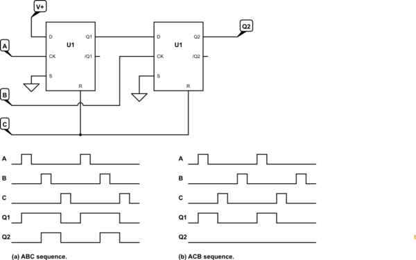
This is very similar to a 3-phase phase sequence detector application. The circuit of Figure 1 will get you most of the way to your requirements.

simulate this circuit – Schematic created using CircuitLab
Figure 1. A single CD4013 dual D flip-flop will suffice.
Q2 will pulse for an ABC rotation. It will remain off for an ACB rotation.
-
\$\begingroup\$ So, how can we get rotation direction, if we are using 120degree phase difference BLDC ? \$\endgroup\$ Commented Nov 9, 2016 at 13:07
-
\$\begingroup\$ What part of the answer do you not understand? \$\endgroup\$ Commented Nov 9, 2016 at 18:13
-
\$\begingroup\$ I understand this application and it works. But in a 120 degree phase BLDC, hall outputs are not the same. Logic high parts of outputs overlap. So, does not function the same. \$\endgroup\$ Commented Dec 5, 2016 at 6:27
-
\$\begingroup\$ That's probably the C input holding the outputs in the reset state. You'll need to add a one-shot or monostable to the C input to give a short reset pulse. The other option is to invert all of the signals. Would that cure the overlap? \$\endgroup\$ Commented Dec 7, 2016 at 19:58
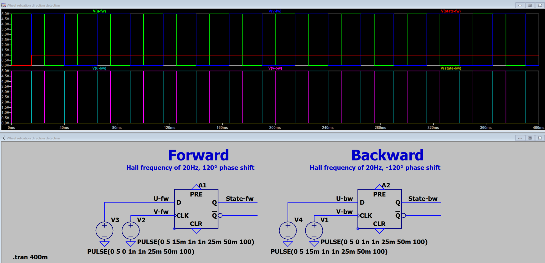
A simple way to do this is by using a D type flip-flop. If the hall effects of your BLDC have 120° phase shift, connect one hall signal to the D input and the other on the CLK input.
The output will be low in a rotation direction and high in the other.

-
\$\begingroup\$ This is the right answer for 120°-duty-cycle Hall signals. \$\endgroup\$– addaonCommented Jul 3, 2022 at 3:39
If you search the literature (e.g: http://www.edn.com/design/sensors/4407580/1/Brushless-DC-Motors-Part-II--Control-Principles), you will find out that there are many copies of the same 'truth table' that give you exactly which switch should be turned on/off in your commutator based on the hall sensor state.
Once you have the truth tables, you can build a basic logic circuit from ANDs, ORs and inverter gates.
