2
\$\begingroup\$

I just built an HTPC. It's got a bright white power-on indicator LED that is in fact needlessly bright and, which is worse, blinks when the pc is in suspend mode. I want it to be less eye-catching.

  • I suppose I can wire a resistor in front of the LED to dim it, but I've no idea how to select the proper value.

(and/or)

  • Can I wire a capacitor in front of the LED to make it's "very binary" blinking into a somewhat smoother wave pattern, sort of pulsating? I really don't care about the specific wave form, I just want it to draw less attention (making it glow constantly, but dimmer, in suspend than in power-on would be just fine, if that's a simpler thing to do).

I've no idea about the ratings of the components involved. I'm sure the LED is being driven at 5V (I can check), and I suppose it draws somewhere between 20 and 200 mA.

Can you help a feller out with some component choices based on such poor specs?

Update: I have soldered together a 2200uF capacitor and two 100k potentionmeters -- see photos here. I have tried to recreate Spehro Pefhany's diagram (dead bug style, it's gloriously hideous) and I can report a 50% success: the dimming works nicely, but the blinking seems to be completely disabled -- it's always on (at whatever brightness I choose) and I can't detect even a hint of variance regardless of how I adjust the 2nd pot.

Have I (despite triple-checking) put it together wrongly? What should I change to restore at least some blinking?

\$\endgroup\$
11
  • 3
    \$\begingroup\$ Ever heard of electrical tape? Put some over the LED. \$\endgroup\$
    – Andy aka
    Commented Mar 1, 2018 at 17:11
  • 1
    \$\begingroup\$ Or just clip the effin' thing off. Damned eye searing high intensity blue LEDs... \$\endgroup\$
    – JRE
    Commented Mar 1, 2018 at 18:51
  • 1
    \$\begingroup\$ hmmm... reminiscing about a time you had a drawer full of floppy disk labels you never used.... \$\endgroup\$
    – Trevor_G
    Commented Mar 1, 2018 at 18:57
  • 1
    \$\begingroup\$ @Trevor_G wot? nail-polish - how did you learn that trick my dear hehe \$\endgroup\$
    – Andy aka
    Commented Mar 1, 2018 at 19:52
  • 1
    \$\begingroup\$ @Andyaka lol..just don't tell the Mrs. \$\endgroup\$
    – Trevor_G
    Commented Mar 1, 2018 at 19:56

4 Answers 4

2
\$\begingroup\$

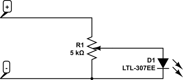
I'd use a 5k potentiometer:

schematic

simulate this circuit – Schematic created using CircuitLab

Adjust brightness as desired by turning the knob. If you want to be fancy, mount the potentiometer so that it is accessible from outside.

\$\endgroup\$
6
  • \$\begingroup\$ Doesn't help the OP's main problem: annoying blinking. \$\endgroup\$
    – awjlogan
    Commented Mar 1, 2018 at 18:18
  • 3
    \$\begingroup\$ Well, you could dim it to a point where it's no longer annoying. \$\endgroup\$ Commented Mar 1, 2018 at 18:20
  • 1
    \$\begingroup\$ Ops main problem is the brightness. If it wasn't as bright the blinking would be ignorance. +1 \$\endgroup\$
    – Passerby
    Commented Mar 1, 2018 at 19:10
  • \$\begingroup\$ Though there is no reason to connect the other end to ground. \$\endgroup\$
    – Passerby
    Commented Mar 1, 2018 at 19:11
  • \$\begingroup\$ @SimonRichter yes, there could well be such a point. At least, this is a good, simple, "version 1". \$\endgroup\$
    – KlaymenDK
    Commented Mar 1, 2018 at 19:51
6
\$\begingroup\$

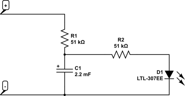
Total guesswork, but brightness is perceived logarithmically so the exact resistor values are not critical.

You could try something like this:

schematic

simulate this circuit – Schematic created using CircuitLab

The 2200uF/6.3V electrolytic capacitor needs to be installed with the correct polarity. Eg. Nichicon UFW0J222MPD.

If you don't like the way it works, change the values (perhaps in steps of 2 or 3:1, don't bother with much less of a change). If you're purchasing parts, get a few values- you can put resistors in series or capacitors in parallel to increase the values.

The "attack" time constant is of the order of RC where R is 50K or less, and it will decay visually slower because the LED current will drop. 2200uF and 25K-50K is only about 20-40 ms so it won't make much difference turning on, but will seem a bit less abrupt turning on and especially going off.

If you decrease the resistors to get more brightness you'll have to increase the capacitor proportionally to get the same time constant and you'll rapidly run out of practical sized capacitors. In such case it might be better to try just a single resistor.

\$\endgroup\$
7
  • 2
    \$\begingroup\$ Mentioning the RC time constant formula and giving some indication of which way to change resistor values to make it smoother, dimmer, or brighter would make this a very helpful answer. \$\endgroup\$ Commented Mar 1, 2018 at 16:15
  • 5
    \$\begingroup\$ @Spehro 102k total series resistance for the LED? Won't the LED light be imperceptible, rather than just dimmed like OP originally wanted? \$\endgroup\$
    – Jim
    Commented Mar 1, 2018 at 16:44
  • \$\begingroup\$ @jim It's possible, though I tried it on a 3mm red and it was quite visible in muted light (as in a tower PC under a desk). \$\endgroup\$ Commented Mar 1, 2018 at 18:09
  • \$\begingroup\$ Thanks for this neat design! A shame that making changes requires balancing all three components, but that's just the nature of the thing (so to be clear, no blame to you). \$\endgroup\$
    – KlaymenDK
    Commented Mar 1, 2018 at 20:18
  • 1
    \$\begingroup\$ @KlaymenDK There are really two variables. Find a resistor value that gives the appropriate brightness, then split that in two equal values and add the capacitor if you still want to soften the blinking. \$\endgroup\$ Commented Mar 2, 2018 at 2:11
1
\$\begingroup\$

It's quite simple: -

enter image description here enter image description here

No soldering, nor CE labels, no messing around. No DVM required for testing. Plus you got refills by the dozen so next time you have a too-bright LED it costs nothing but time remembering where you slid the pack of these little beauties.

It costs about 4 quid from here and here's the originator's web site.

Don't try it with high power lasers though (I mean... who would?).

\$\endgroup\$
2
  • \$\begingroup\$ Ha... figures somebody would productize it. \$\endgroup\$
    – Trevor_G
    Commented Mar 1, 2018 at 20:02
  • \$\begingroup\$ It's "only" 4 quid ... I can't imagine that being very expensive to put on a shelf, so good product (for them)! I have a ton of small round stickers and have already used this solution elsewhere. Doesn't address the blinking, though. \$\endgroup\$
    – KlaymenDK
    Commented Mar 1, 2018 at 20:52
1
\$\begingroup\$

First of all, measure the voltage just to be sure of the LED supply voltage. If you can, find the resistor that is limiting the current, then measure the voltage drop across the LED. It shouldn't be too difficult to find if you get a multimeter with a continuity buzzer and can get a probe on the LED. This will give you the necessary numbers to calculate the current driving the LED. Then you can just use a simple calculation to find the resistor you need to limit the current to whatever you want it to be! Rled = (Vs-Vf)/I, where Vs is the supply voltage and Vf is the forward voltage of the LED.

I'm not too sure about wiring a capacitor in front of the LED, it would depend on the resistor in front of it, and how quick the LED blinks. You could play around with some values, or attempt to calculate it, by using the capacitor discharge equation (V = Vs*e^(-t/RC)) and transpose for C...... but that may be a bit too time consuming, so maybe just play around till you get something you feel is good!

There may be better ways, but this is how I would do it.

\$\endgroup\$
3
  • 2
    \$\begingroup\$ "find the resistor that is limiting the current" - uh, sorry no. This LED is connected to a pc motherboard. I've no chance of correctly figuring out which resistor goes where. \$\endgroup\$
    – KlaymenDK
    Commented Mar 1, 2018 at 19:54
  • \$\begingroup\$ Fair enough.... then add a potentiometer till you're happy with the brightness \$\endgroup\$
    – MCG
    Commented Mar 2, 2018 at 0:05
  • \$\begingroup\$ Although a multimeter with a continuity buzzer should enable you to be able to do it \$\endgroup\$
    – MCG
    Commented Mar 2, 2018 at 10:27

Your Answer

By clicking “Post Your Answer”, you agree to our terms of service and acknowledge you have read our privacy policy.

Not the answer you're looking for? Browse other questions tagged or ask your own question.