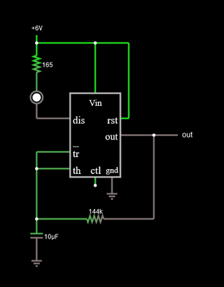
I would like to ask you guys to comment a bit. Does it work in real life? I would like to use a 555 in astable mode with the same time intervals for on and off (both 1s) and let a Vishay diode flash. I know it is not 100% possible to have the same time intervals because \$R_a\$ would have to go to \$0Ω\$ which would not let the timer work. As most of you already know, I use PSpice for Ti2020 and therefore do not have all the components imaginable. I had to create a "LED" myself. But should fit like that.
My knowledge comes from this website. It is a German text, but the formulas are the same. ✌️
I arbitrarily chose 6V as the input voltage. The series resistor in front of the LED is \$165Ω\$, so that no more than 20mA can flow through – as specified in the data sheet.
\$(3.947V-0.74V)/0.020A = 160Ω\$ And I chose 165Ω for safety reasons.
\$C_3\$ and \$C_4\$ are backup capacitors. According to the website, one should use them.
Can you eliminate the small spikes during the switch-on and off processes? (see images)
I know there is no \$143919.5Ω\$ resistor, this is just playing with numbers.
current through LED
555 Out Voltage
Based on Spehro Pefhany's answer, I have now done the following:
I simulated a real LED (forward voltage starting with 3.2V and a maximum of 3.9V). The LED gets its 20mA. I was able to reduce the base resistance a bit, but so that the timer does not lose more than 1mA.


