0
\$\begingroup\$

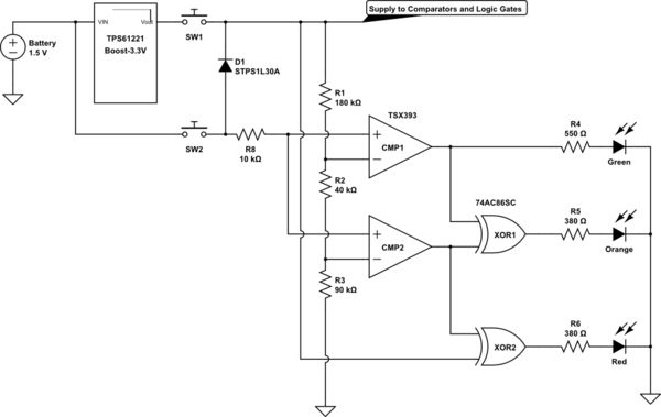
I'm designing a small system that uses an ATMEGA328P and a LoRa module that runs on 3.3V using a AAA 1.5V battery. The battery is connected to a Boost Converter which steps up the 1.5V to 3.3V to power the entire system. So obviously the whole system needs to have a low power consumption to save battery power. I want to attach a push button in the circuit that displays the battery level when pressed through LEDs.

The LED indicators are as follows.

  • Green LED - V_Bat > 1.4V
  • Yellow LED - 0.9V < V_Bat < 1.4V
  • Red LED - V_Bat < 0.9V

Here is the design of my circuit using the following components

schematic

simulate this circuit – Schematic created using CircuitLab

Here are my questions.

  1. Will the circuit work?
  2. Will the components I picked out worked? (I picked components that are all low power)
  3. Are there any necessary resistors or passive components needed in the circuit to limit current anywhere?
  4. In my voltage divider, how high can I set the resistors to reduce power consumption before it starts giving problem?
  5. Any suggestions to improve the circuit?

Thanks for the help in advance and sorry for the many questions

\$\endgroup\$
12
  • 3
    \$\begingroup\$ That will very likely work fine. However, since an ATMEGA328 is already there, I would just connect the battery to an analog input and write some code that does the measurement when you press the button (also connected to the ATMEGA328). This of course assumes that you still have some pins left on the ATMEGA. \$\endgroup\$ Commented Jun 28, 2018 at 9:12
  • \$\begingroup\$ Thanks, that was actually my backup-plan. However, I'm trying to avoid using the ATMEGA as it will require it to wakeup from sleep mode and run a code which will cause it to draw more power. \$\endgroup\$
    – Max
    Commented Jun 28, 2018 at 9:39
  • \$\begingroup\$ if you use common anode red-green LED you only need two comparators, (and no gates) but you'll annoy the colour-blind. \$\endgroup\$ Commented Jun 28, 2018 at 9:45
  • \$\begingroup\$ nice circuit - simple and elegant if you don't mind the component count. But - where the output of the switch goes to XOR2, the vertical wire - are those nodes to the battery output? Looks like a diagram error. That shorts the battery to the 3.3V. \$\endgroup\$
    – danmcb
    Commented Jun 28, 2018 at 9:47
  • 1
    \$\begingroup\$ @dmb is right, the dots should not be there! Also, I see another issue (yes even though I said it looked fine) there will be a current flowing into the inputs of the comparators when they have no supply voltage! This current is caused by the ESD diodes between inputs and supply pins. You should be very careful when applying a voltage to chips that do not have a supply voltage! See the EEVBlog video about this: youtube.com/watch?v=2yFh7Vv0Paw&t=3s and yes that applies to all chips not only micros. \$\endgroup\$ Commented Jun 28, 2018 at 9:54

3 Answers 3

2
\$\begingroup\$

It looks good but there is a problem as spotted by @Bimpelrekkie above - the comparator inputs always have volts applied, which means they will draw current and may fail as you violate the max ratings at the input.

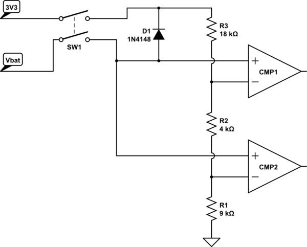
This modification should correct those problems:

schematic

simulate this circuit – Schematic created using CircuitLab

Now the circuit is completely isolated when the (double pole) switch is not pressed. The diode protects the comparator inputs, given that the two poles of the switch will not close at exactly the same time.

\$\endgroup\$
9
  • \$\begingroup\$ Strictly speaking, adding the DPST switch and diode does not satisfy the data sheet requirement that the input voltage never exceed the supply voltage...you still have the inputs above the supply voltage by a diode's forward voltage. I think in this case you can just add a 10k resistor between the battery and the comparators to limit the current that flows through the internal ESD diodes. I'll admit that the datasheet doesn't appear to give any guaranteed options here. \$\endgroup\$ Commented Jun 28, 2018 at 11:26
  • \$\begingroup\$ or simply scan around for another comparator that is a bit more understanding. I think it's worth making this circuit work, it has the great benefit of simplicity. \$\endgroup\$
    – danmcb
    Commented Jun 28, 2018 at 11:35
  • \$\begingroup\$ Thanks for the circuit @dmb. I can use a low forward voltage diode of about 0.3V and attach the 10k resistor as recommended by Elliot Alderson. This should only cause the supply voltage to be higher than the input by a small amount for a short time. If I have to look for another comparator, what should I be looking for in its datasheet? \$\endgroup\$
    – Max
    Commented Jun 29, 2018 at 4:00
  • \$\begingroup\$ You're welcome. Look for absolute max ratings for voltage on the + and - inputs. Ideally you want one that can take Vcc + 0.7V (as well as being able to operate at 3V3 of course). If you use a schottky diode instead of 1N4148, you can drop that to Vcc + 0.3V or so. \$\endgroup\$
    – danmcb
    Commented Jun 29, 2018 at 4:54
  • \$\begingroup\$ I have redesigned the schematic based on your recommendations and I have re-pick the comparator. Based on this comparator datasheet, it states that the input voltage may exceed the supply voltage as long as its within the common-mode voltage. I also picked a diode with low a forward voltage and put the selected LEDs for the circuit. My only concern now is, if the op-amp can supply enough current to light up the green LED. \$\endgroup\$
    – Max
    Commented Jul 2, 2018 at 3:50
0
\$\begingroup\$

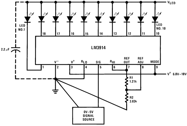
You could use the LM3914 (or similar) that is designed for this sort of application -

enter image description here

There are lots of examples in the datasheet

You could obviously modify an example to just have 3 LEDs.

\$\endgroup\$
0
\$\begingroup\$

I'm not sure you will get enough current to illuminate your LEDs. The comparator datasheet specifies that the output voltage will be at least 1.8V when sourcing 4mA. That same 4mA passing through 150\$\Omega\$ will drop an additional 0.6V so you may not even get your green LED to light up. This circuit might work as a one-off hack if you omit the resistors and use low current LEDs but I wouldn't use it for a mass-produced product.

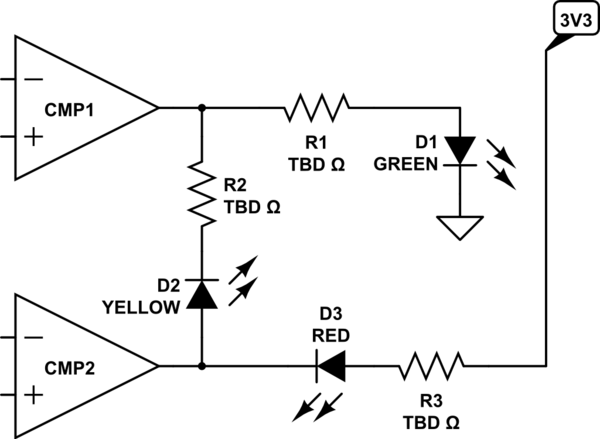
I don't think you need the XOR gates. The top comparator's output would go to the green LED's anode, as you have shown. Connect the yellow LED's anode to the output of the bottom comparator and its cathode to the output of the top comparator. Connect the red LED's anode to the 3.3V supply and its cathode to the output of the bottom comparator. Suitable current limiting resistors will be needed, of course.

schematic

simulate this circuit – Schematic created using CircuitLab

\$\endgroup\$
6
  • \$\begingroup\$ This answer is objectively wrong and speculative. \$\endgroup\$
    – Joe S
    Commented Jun 28, 2018 at 11:53
  • 1
    \$\begingroup\$ @JoeS Your comment is unsubstantiated and valueless. So educate me. Correct my reading of the datasheet and Ohm's law calculations. \$\endgroup\$ Commented Jun 28, 2018 at 11:59
  • \$\begingroup\$ I actually like this circuit also and would like to know what @JoeS means by that it wont work. \$\endgroup\$
    – Max
    Commented Jun 29, 2018 at 4:12
  • \$\begingroup\$ @ElliotAlderson Sorry if this is a stupid question as I'm not very familiar with powering LEDs direct from logic gates. Which part of the datasheet did you see that it states minimum voltage 1.8V? How I calculated the values were by assuming my LEDs use around 5mA with a forward voltage of 1.8V since they are only indicator LEDs. Then from the datasheet it says VOH is 2.56V running at 24mA. So based on that I calculated the resistor to be about 150 ohms. Is this wrong? \$\endgroup\$
    – Max
    Commented Jun 29, 2018 at 4:58
  • \$\begingroup\$ @Max Your green LED runs directly off of the comparator, so you need to use the \$V_{OH}\$ for that component. I was mistaken to say that the red LED wouldn't light, it is the green. Oh, and you get 12mA from the '86 when used at 3V. It's hard to say if the resistor values are correct without data on the LEDs. \$\endgroup\$ Commented Jun 29, 2018 at 11:28

Your Answer

By clicking “Post Your Answer”, you agree to our terms of service and acknowledge you have read our privacy policy.

Not the answer you're looking for? Browse other questions tagged or ask your own question.