1
\$\begingroup\$

Some background, I have a tractor that I want to make semi-autonomous.

The tractor has it own PLC and an NPN Proximity sensor to measure speed.

I have industrial PLC by Unitronics (V130) with I/O that can act as NPN or PNP. I wish to connect my PLC to the same sensor and save me a hassle to install another one next to it.

I wonder if it safe (no harm to a sensor or either of the PLC) to split the sensor wires and if it possible to sense the sensor in both PLC?

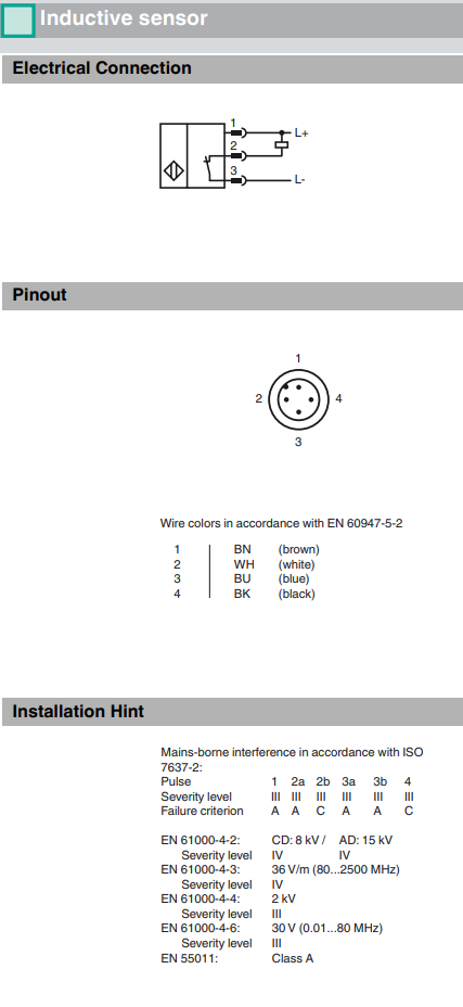
The sensor model is NBN8-12GM50-E1-V1 by Pepperl-Fuchs Datasheet: https://files.pepperl-fuchs.com/webcat/navi/productInfo/edb/293454-0057_eng.pdf?v=20180423144546

EDIT: The two PLCs don't share the same power source and ground

Some electrical data from datasheet

Thank you

\$\endgroup\$

3 Answers 3

1
\$\begingroup\$

I wonder if it safe (no harm to a sensor or either of the PLC) to split the sensor wires and if it possible to sense the sensor in both PLC?
...
EDIT: The two PLCs don't share the same power source and ground

If the PLC's do not share the same ground, it is electrically not possible to share this sensor.
Depending on the frequency of the signal this could be solved by using isolators or optocouplers. But read below...


Aside from electrical compatibility, what about functional compability?
Is it disirable that two PLCs, for different functionalities share a sensor?
What if a mechanic for system A replaces the sensor, being unaware that system B relies on it?

I would place a secondary sensor. All problems avoided.

\$\endgroup\$
1
\$\begingroup\$

If the two systems share a common negative then yes, if the PLC has an NPN (sourcing) input but it could cause problems.

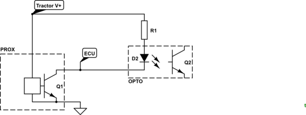
schematic

simulate this circuit – Schematic created using CircuitLab

Figure 1. Opto-isolated feed to PLC.

With the addition of a resistor and opto-isolator you can ensure trouble-free operation due to the complete isolation between the two systems.

  • Calculate R1 to give about 10 mA through D2. D2, being an infrared LED will drop about 1.4 V at this current.
  • Q2 can be connected to the PLC input and common but observe correct polarity. One of the beauties of this arrangement is that Q2 can drive a PNP (sinking) or NPN (sourcing) input.
\$\endgroup\$
2
  • \$\begingroup\$ Cool solution, by the way, my plc don't share the same source power or common negative. \$\endgroup\$ Commented Aug 9, 2018 at 7:47
  • 1
    \$\begingroup\$ Then this is the way to go. Don't forget to accept an answer if it solves your problem. \$\endgroup\$
    – Transistor
    Commented Aug 9, 2018 at 10:39
1
\$\begingroup\$

It looks extremely likely you can connect two loads to the unit:

enter image description here

The output is an NPN transistor with a maximum load specified to support 200mA to ground. You PLC inputs will have either an onboard pullup resistor or you get to add one externally.
It's extremely unlikely that you have anywhere near the maximum load in your current configuration.

If you want to test it, measure your output with an oscilloscope and then attach your second PLC load and ensure you still meet the <2V low signal. If the input resistor (pullup) is configurable in you PLC, then you only need 1 resistor configured for the two inputs.

\$\endgroup\$
2
  • \$\begingroup\$ Thank you for the detailed information, Is it ok if both PLC has an internal pull-up resistor enabled? \$\endgroup\$ Commented Aug 9, 2018 at 7:42
  • 1
    \$\begingroup\$ @OrHirshfeld Yes, providing the sensor does not have to sink more than 200mA. Just disconnect the sensor and use a multimeter (on current setting) to shorth the inputs to ground to test the current. \$\endgroup\$ Commented Aug 9, 2018 at 14:38

Your Answer

By clicking “Post Your Answer”, you agree to our terms of service and acknowledge you have read our privacy policy.

Not the answer you're looking for? Browse other questions tagged or ask your own question.