1
\$\begingroup\$

I am trying to design a 1 DOF copter as in this drawing: enter image description here
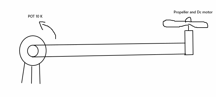
For this circuit there is a stick connected to a DC motor and potentiometer. The potetiometer can be rotated. I need to control the position of the motor with analaog PID circuit using another potentiometer.

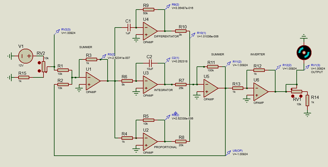
My PID circuit is as below:

enter image description here

The first potentiometer controls the angle. The output potentiometer should give feedback.

I am newbie and this circuit does not work, that means my motor does not work when I supply power.

I checked without the motor connected. There is a voltage and everything is okay but after connecting the motor, the voltage is zero and the system does not work.

Because of the pandemic situation, I cannot use the lab equipment to power supply. I think there is not enough current.

  • How can I increase the current?
  • How can I make sure the PID circuit is working correctly?

Some information my circuit components:

  • All op-amps UA741cp
  • Other component same with the designed circuit in picture
  • My motor is 820 coreless brushed motor set 3.3V =35000-37000 RPM, 5V = 50000 RPM , Size:8 x 20mm, working current min = 0.15A, weight 6.5gr
\$\endgroup\$
4
  • 1
    \$\begingroup\$ There's no way you can drive that motor directly from the opamp output. The 741 can deliver a few milliamperes at most. The motor needs much more current than that. \$\endgroup\$
    – JRE
    Commented May 8, 2021 at 17:07
  • \$\begingroup\$ Do you suggest an opamp type? \$\endgroup\$ Commented May 8, 2021 at 17:31
  • 1
    \$\begingroup\$ There's multiple things wrong with that circuit. Please edit your question with a revised schematic that shows how the op-amps are getting power, and where the motor is in the circuit. Do you even have power to the op-amps? \$\endgroup\$
    – TimWescott
    Commented May 8, 2021 at 17:33
  • \$\begingroup\$ Okay! I updated the schema and it works very well right now in simulation. Now I will set up the reality of the scheme. \$\endgroup\$ Commented May 8, 2021 at 17:40

3 Answers 3

2
\$\begingroup\$

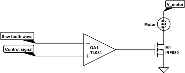
To increase the current, I suggest to use PWM-signal by using output (voltage) signal compare with saw-tooth or triangle signal. Then you can feed PWM signal to Motor drive module or FET to drive motor. This PWM method produce less heat compare linear method.

schematic

simulate this circuit – Schematic created using CircuitLab

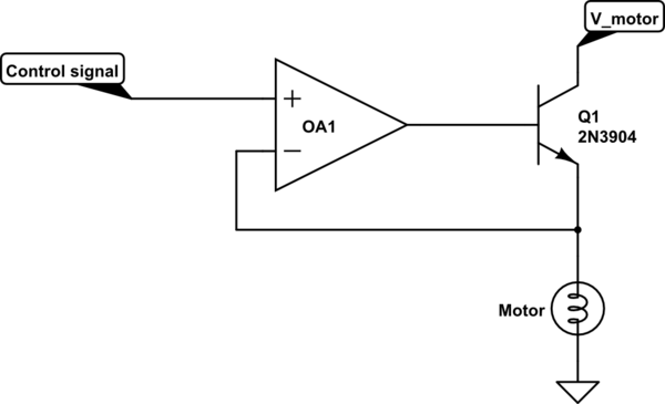
If you really want to drive motor with voltage you can try linear voltage regulator with loss a lot of power to heat as follow.

schematic

simulate this circuit

If you want to make sure that your PID control work currectly , you can test open-loop response with signal generator and osciloscope.

\$\endgroup\$
3
  • \$\begingroup\$ This comment was very useful for my research, thanks. \$\endgroup\$ Commented May 8, 2021 at 19:20
  • 1
    \$\begingroup\$ Please add a flyback diode across the motor. \$\endgroup\$
    – winny
    Commented Jul 23, 2021 at 21:05
  • \$\begingroup\$ Thank for remind, using light bulb symbol make me totally forgot to add flyback diode. \$\endgroup\$
    – M lab
    Commented Jul 30, 2021 at 4:06
1
\$\begingroup\$

High current from an op amp with or without transistors?

As for testing. Break the problem down into sections and test each section. To test the control loop, that gets a bit tricky, so start with just the P term. Then add the I term. The D term is last. Adjust the coefficients at each stage.

Understand that adjusting a real PID system is not trivial, so expect to make mistakes.

\$\endgroup\$
1
  • \$\begingroup\$ Thank you for your valuable comment, I will add it here as a reply when I complete the system, but what a voltage source and current value should I have in order to run this circuit, I cannot reach the laboratory due to the pandemic. Now I have a small source that gives current up to 12v and 1 amp, I will get a stronger one, I would be glad if you have suggestions as a component (op-amp type). \$\endgroup\$ Commented May 8, 2021 at 17:38
0
\$\begingroup\$

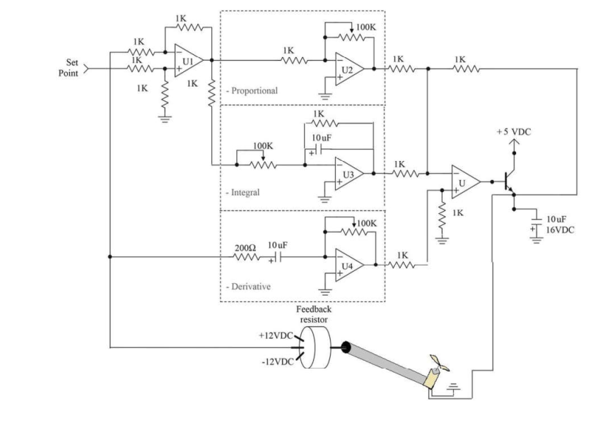
enter image description here

This circuit works well for me. I use five LM741 op-amps and one power BJT for motor driving.

\$\endgroup\$

Your Answer

By clicking “Post Your Answer”, you agree to our terms of service and acknowledge you have read our privacy policy.

Not the answer you're looking for? Browse other questions tagged or ask your own question.