1
\$\begingroup\$

Recently I am working on a controller to drive a PWM fan (datasheet). I am using a atmega32u4 and it sends a 25khz PWM signal to the fan and it's working well. I want the fan to be off when I cut the power to the controller, so I added a pull down resistor like below:
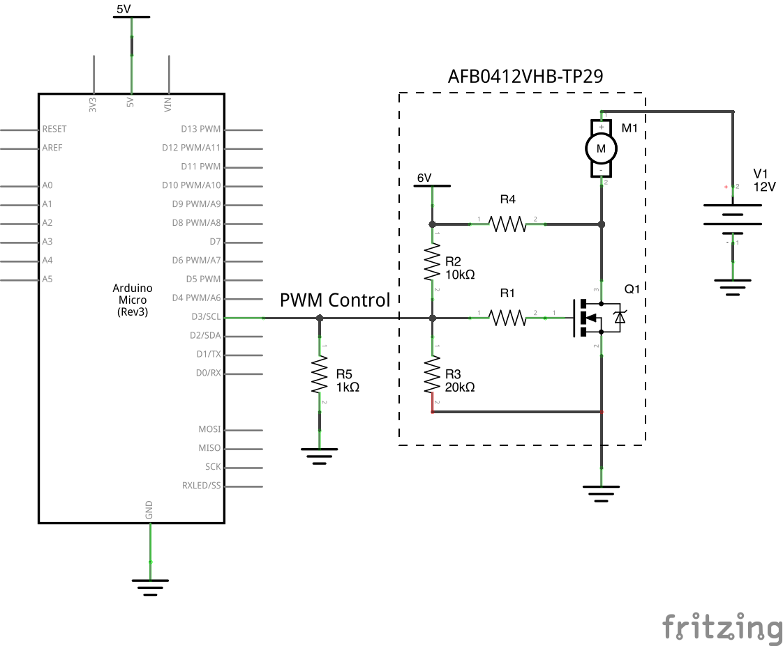
enter image description here

So my questions are:

  1. is the choice of the pull down resistor correct? It pulls down the PWM control to 0.52V (need to be less than 0.8V according to the data sheet) when the atmega32u4 is powered off. OTOH when the atmega32u4 is on, it pulls down the high signal from D3 from 5V to 4.8V

  2. do i need to add a diode in front of D3? Will it be considered harmful if there's possibility a current flowing back from the PWM control wire to D3 when the atmega32u4 is off?

I am a newbie to electronic and I want to learn how to make my circuit correct and safe. Will be very grateful if my questions can be answered.

\$\endgroup\$
0

1 Answer 1

-1
\$\begingroup\$

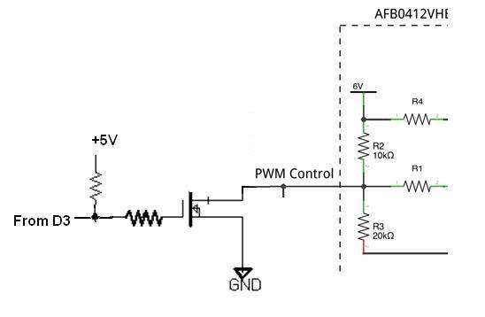
Have a look at the below corrected diagram . 1). You should add a freewheeling diode at the motor terminal to catter inductive kicks. 2)If you need further protection you can isolate the microcontroller section from the MOSFET via an optocoupler, and there power supplies respectively. 3) Add a zener at the base of the Mosfet to protect the gate at what ever, voltage you are operating the FET.You may also try adding an inverter stage to switch off the FET on power off. @Ivan ,I missed your datasheet anyways, Try using an inverter in between D3 and rest of the ckt of yours. Sometyhing like this; enter image description here

\$\endgroup\$
6
  • \$\begingroup\$ you should read the OP's linked datasheet. THe circuitry you're marking up is the representation of the circuity inside the fan! \$\endgroup\$
    – DoxyLover
    Commented May 18, 2014 at 17:02
  • \$\begingroup\$ Thanks for your reply Adi. As DoxyLover pointed out whatever in the box is actually inside the fan "AFB0412VHB-TP29". But I believe it must be incomplete and simplified - I copied it from the bottom of page 9 of the datasheet and the purpose is to illustrate the input impedance of the PWN control lead wire. I didn't dissemble it as it's not a very cheap fan and I don't want to buy a spare one, but I think there should be at least a fly back diode and more components inside the fan than what I put in the simplified schematic. \$\endgroup\$
    – ivan
    Commented May 18, 2014 at 21:38
  • \$\begingroup\$ Could you please explain what the invert does and how it will solve my problem? \$\endgroup\$
    – ivan
    Commented May 20, 2014 at 10:06
  • \$\begingroup\$ No worries. I think I get the idea: the inverter is for reverting the pulled up input when D3 is floating and the motor will stop. Since the pull up resistance can be much larger than 1k (the one I use for pull down) the current can be well limited. However in my application 5V will go away at the same time when the AVR is off. \$\endgroup\$
    – ivan
    Commented May 31, 2014 at 5:54
  • \$\begingroup\$ If you have 12V available on your motor side , you can use a 12V>5V regulator for pullup. \$\endgroup\$
    – Adi
    Commented May 31, 2014 at 7:22

Your Answer

By clicking “Post Your Answer”, you agree to our terms of service and acknowledge you have read our privacy policy.

Not the answer you're looking for? Browse other questions tagged or ask your own question.