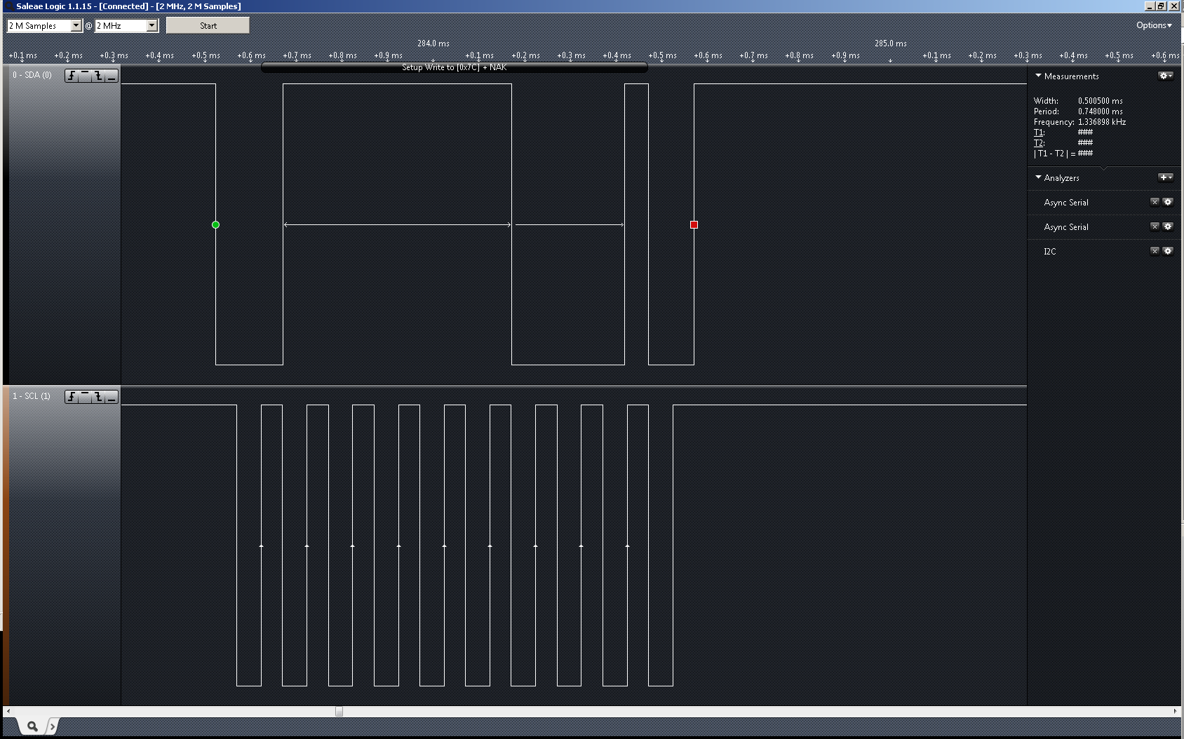
I'm trying to control an I2C Enabled LCD Display using the STM32F0. I have a bunch boards built with the LCDs and a couple of them work all the time, a few work intermittently and a few rarely work at all and I'm not sure where the issue is coming from.
I've tried analyzing the I2C lines and sometimes I see the display NACKing while othertimes I see it ACK but the I2C just stops. Sometimes I even see a bunch of unexpected data being sent.
I'm trying to figure out if this is a hardware issue, LCD issue, or FW issue to start with. From a hardware perspective I've followed the recommended circuit on the datasheet and used ~6k pull-ups. I can only assume the LCD itself is working since sometimes I can get it to display properly. This leads me to believe it's a FW issue. I've noticed that if I play around with the delays between messages I can get it to work sometimes and I can certainly break it. Is there any more error checking or similar that I should be doing do on the uC to improve reliability?

void I2C_LowLevel_Init(void)
{
  GPIO_InitTypeDef  GPIO_InitStructure;

  /* Configure the I2C clock source. The clock is derived from the HSI (8MHz default)*/
  RCC_I2CCLKConfig(RCC_I2C1CLK_HSI);

  /* LCD_I2C_SCL_GPIO_CLK and LCD_I2C_SDA_GPIO_CLK Periph clock enable */
  RCC_AHBPeriphClockCmd(LCD_I2C_SCL_GPIO_CLK | LCD_I2C_SDA_GPIO_CLK, ENABLE);

  /* LCD_I2C Periph clock enable */
  RCC_APB1PeriphClockCmd(LCD_I2C_CLK, ENABLE);

  /* Connect PXx to I2C_SCL*/
  GPIO_PinAFConfig(LCD_I2C_SCL_GPIO_PORT, LCD_I2C_SCL_SOURCE, LCD_I2C_SCL_AF);

  /* Connect PXx to I2C_SDA*/
  GPIO_PinAFConfig(LCD_I2C_SDA_GPIO_PORT, LCD_I2C_SDA_SOURCE, LCD_I2C_SDA_AF);

  /* GPIO configuration */
  /* Configure LCD_I2C pins: SCL */
  GPIO_InitStructure.GPIO_Pin = LCD_I2C_SCL_PIN;
  GPIO_InitStructure.GPIO_Mode = GPIO_Mode_AF;
  GPIO_InitStructure.GPIO_Speed = GPIO_Speed_2MHz;
  GPIO_InitStructure.GPIO_OType = GPIO_OType_OD;
  GPIO_InitStructure.GPIO_PuPd = GPIO_PuPd_NOPULL;
  GPIO_Init(LCD_I2C_SCL_GPIO_PORT, &GPIO_InitStructure);

  /* Configure LCD_I2C pins: SDA */
  GPIO_InitStructure.GPIO_Pin = LCD_I2C_SDA_PIN;
  GPIO_Init(LCD_I2C_SDA_GPIO_PORT, &GPIO_InitStructure);
}


void I2C_Initialize(void)
{
  I2C_InitTypeDef  I2C_InitStructure;

  I2C_LowLevel_Init();

  /* I2C configuration */
  /* LCD_I2C configuration */
  I2C_InitStructure.I2C_Mode = I2C_Mode_I2C;
  I2C_InitStructure.I2C_AnalogFilter = I2C_AnalogFilter_Enable;
  I2C_InitStructure.I2C_DigitalFilter = 0x00;
  I2C_InitStructure.I2C_OwnAddress1 = 0x00;
  I2C_InitStructure.I2C_Ack = I2C_Ack_Enable;
  I2C_InitStructure.I2C_AcknowledgedAddress = I2C_AcknowledgedAddress_7bit;
  I2C_InitStructure.I2C_Timing = I2C_TIMING;

  /* Apply LCD_I2C configuration after enabling it */
  I2C_Init(LCD_I2C, &I2C_InitStructure);

  /* LCD_I2C Peripheral Enable */
  I2C_Cmd(LCD_I2C, ENABLE);

  /* Select the LCD device address */
  I2C_Address = I2C_HW_ADDRESS;
  Delay(10);
}

uint32_t LCD_Initialize(void)
{
  static int initBuffer[8] = {0x14, LCD_CONTRAST_RESET, 0x5E, 0x6D, LCD_DISPLAY_ON, LCD_CLEAR, 0x06};
  static char welcomeMessage1[LCD_MAX_LINE_SIZE + 1] = "HELLO WORLD";
  int n = 0;

  /* Send Start Bit and I2C Device Address */
  I2C_TransferHandling(LCD_I2C, (LCD_DEVICE_ADDRESS << 1), 10, I2C_AutoEnd_Mode, I2C_Generate_Start_Write);

  /* Wait for TXIS to be set */
  //lcdTimeout = LCD_LONG_TIMEOUT;
  while(I2C_GetFlagStatus(LCD_I2C, I2C_ISR_TXIS) == RESET)
  {
    //if((lcdTimeout--) == 0) return LCD_INITIALIZE_FAIL;
  }

  I2C_SendData(LCD_I2C, 0x00);          /* CMD Byte- Only Data to Follow */
  Delay(1);
  I2C_SendData(LCD_I2C, LCD_BASIC_CONFIG);
  Delay(10);
  I2C_SendData(LCD_I2C, LCD_EXTENDED_CONFIG);
  Delay(10);

  /* Send Remaining Initialization Buffer Data */
  for (n=0; n<7; n++)
  {
    I2C_SendData(LCD_I2C, initBuffer[n]);
    Delay(1);
  }

  Delay(10);


  /* Display welcome message to confirm LCD initialization */
  LCD_Display(LCD_LINE1_START, welcomeMessage1);
  Delay(1000);
  LCD_Clear();
  return LCD_INITIALIZE_PASS;
}
