0
\$\begingroup\$

I am attempting to configure an LCD with just IC chips and I've been having problems. I've worked out that the main problem I am having is in the initialization of the lcd. It needs a goodly amount of time to initialise, and then in needs a couple of more configuration instructions.

I would like to give the lcd time to initialise at startup, and then change to a regular clock pulse after 3 delays. So rather than the regular clock pulse (shown in red) 3 long pulses, then back to the regular 555 spacing (shown in blue). enter image description here
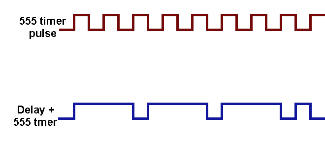
Is there anyway to do this using a combination of IC chips? The delay on the bottom of the clock cycle could be the same long delay, the off time isn't really relevant.

\$\endgroup\$
4
  • \$\begingroup\$ You can do this with one "IC chip", if that chip is a microcontroller. That's really the way to go for applications like this. \$\endgroup\$ Commented Mar 5, 2021 at 13:18
  • \$\begingroup\$ Which edge is active and which delay does not matter 1? 0? \$\endgroup\$
    – D.A.S.
    Commented Mar 5, 2021 at 13:52
  • \$\begingroup\$ It works on the rising edge, and the distance between the falling edge and the next rising edge. (In blue you can see they are short just like the timer. \$\endgroup\$ Commented Mar 5, 2021 at 15:37
  • \$\begingroup\$ I'm doing this as an exercise in not using a microcontroller. \$\endgroup\$ Commented Mar 5, 2021 at 15:38

2 Answers 2

1
\$\begingroup\$

The blue trace is one output pulse every 2.5 input pulses, not one every three. This would take a lot of gating to decode.

For 1-out-of-3, consider the CD4017 Johnson counter. If you OR gate or diode-OR together outputs 1, 4, and 7, that is the blue trace. Output 8 inhibits counting and addresses a mux that switches from the output of the OR gate to the red signal (the 4017 clock input). Not elegant, but functional.

\$\endgroup\$
0
\$\begingroup\$

You can use a sequencial timer like in 9.2.4 of ne555 datasheet (Texas instruments) to control two MOSFET (like 2n7000) who switch between two circuit R es Capa and Diodes as input of your ne555 Clock. Or just change the voltage of the Ctrl (ie: 8/10 of VCC) pin of your clock to increase the duty cycle and lower the frequency.

\$\endgroup\$

Your Answer

By clicking “Post Your Answer”, you agree to our terms of service and acknowledge you have read our privacy policy.

Not the answer you're looking for? Browse other questions tagged or ask your own question.