2
\$\begingroup\$

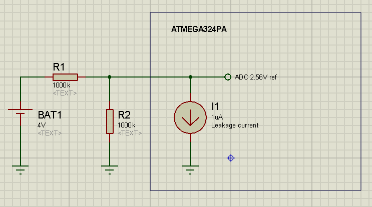
I'm using the internal ADC of an ATMEGA324PA to measure the voltage of a low power 3.6V battery. The ADC is referenced to it's internal 2.56V and I need to use a voltage divider on the battery.
To not draw too much current form battery I'm using large value resistors, but this is a problem, because the ADC input pin on uC is leaking at the most 1uA (according to the datasheet - page 328).

This can easily be compensated in the code, but is this leakage current constant? Does it vary with temperature, Vcc, etc. How much does it vary? Is this leakage caused by the input pin protection diodes (page 74)?

enter image description here

\$\endgroup\$
2
  • \$\begingroup\$ Why not use a voltage follower? \$\endgroup\$ May 30, 2014 at 17:04
  • \$\begingroup\$ @IgnacioVazquez-Abrams Already built the board. So I'm hacking 2 small resistor on top. \$\endgroup\$
    – Chris
    May 30, 2014 at 17:08

2 Answers 2

2
\$\begingroup\$

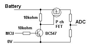
You could use a P channel MOSFET for connecting the battery to a lower resistance potential divider but it would need a spare GPIO line: -

enter image description here

The TPS1110 has a leakage current less than 100 nA so it won't draw too much from the battery.

\$\endgroup\$
1
  • \$\begingroup\$ Can't really modify the circuit, it's already built. I'm just trying to compensate for the current leakage in the code and I'm concerned that it's not constant. \$\endgroup\$
    – Chris
    May 30, 2014 at 17:19
2
\$\begingroup\$

Most microcontroller ADC inputs are not buffered. That means that the internal S/H capacitor must be charged directly by the input source.

From the datasheet you linked:-

The Analog Input Circuitry for single ended channels is illustrated in Figure 22-8. An analog source applied to ADCn is subjected to the pin capacitance and input leakage of that pin, regardless of whether that channel is selected as input for the ADC. When the channel is selected, the source must drive the S/H capacitor through the series resistance (combined resistance in the input path). The ADC is optimized for analog signals with an output impedance of approximately 10 kΩ or less. If such a source is used, the sampling time will be negligible. If a source with higher impedance is used, the sampling time will depend on how long time the source needs to charge the S/H capacitor, with can vary widely. The user is recommended to only use low impedant sources with slowly varying signals, since this minimizes the required charge transfer to the S/H capacitor. If differential gain channels are used, the input circuitry looks somewhat different, although source impedances of a few hundred kΩ or less is recommended.

Leakage, per se, is far from being constant, it will vary enormously from one unit to the next and will increase exponentially with temperature, but as I point out above, it's not your only problem.

Suggest you put a buffer amplifier in there or switch the divider as Andy suggested in order to reduce the impedance seen at the ADC input to 10K or less.

If you are powering the micro directly from the battery, a modification of Andy's suggestion would be to wire the lower resistor of the divider to an unused port pin rather than ground. Float the pin to turn the divider off, bring it low to turn the divider on. Then you could use a couple of 20.0K resistors for the divider and meet the 10K input spec. You can see from 28.1.8 that the pin will pull it pretty close to ground typically (not as good as a discrete MOSFET, but there you go).
\$\endgroup\$
4
  • \$\begingroup\$ So the leakage is cause by the input protection diodes (you said exponential dependency with temp). The sampling time is not important, and I'm measuring a DC voltage so it's not that crucial. \$\endgroup\$
    – Chris
    May 30, 2014 at 17:41
  • \$\begingroup\$ I doubt the leakage is your main problem, at room temperature. \$\endgroup\$ May 30, 2014 at 17:47
  • \$\begingroup\$ The difference between units it's not a problem, this is a one time home hack. \$\endgroup\$
    – Chris
    May 30, 2014 at 17:48
  • \$\begingroup\$ I doubt the leakage is your main problem, at room temperature. If you slow the ADC readings down dramatically (both rate and S&H time) it may behave better, also a 100n or so capacitor across R2). \$\endgroup\$ May 30, 2014 at 18:02

Your Answer

By clicking “Post Your Answer”, you agree to our terms of service and acknowledge you have read our privacy policy.

Not the answer you're looking for? Browse other questions tagged or ask your own question.