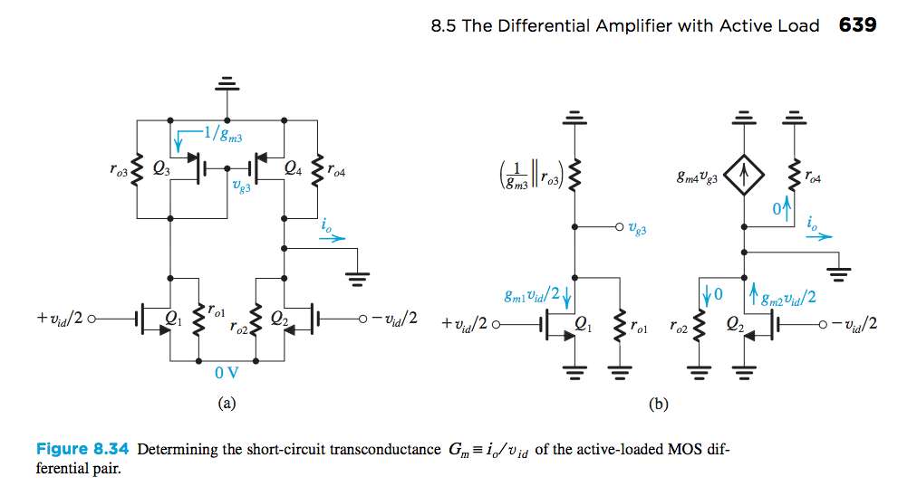
Still, I cannot understand why Q2 isn't cut off with Vds=0.
It's clear that both schematics are AC circuit representaions since all supply voltages have been replaced with AC grounds, i.e, there are no DC sources, voltages or currents present - these have been hidden but not assumed to be zero.
So, in these circuits, we're only considering the variations of voltages and currents about their quiescent values.
Remember, the AC small-signal model and approximation is valid only if the transistors are not cut-off. Indeed, it is assumed that the signal voltages and currents are small compared to the quiescent voltages and currents.
In the schematic on the right hand side, the fact that \$v_{ds2} = 0\$ simply means that the total voltage \$v_{DS2} = V_{DS2} + v_{ds2}\$ is constant, i.e., there is no AC small-signal voltage present, only the quiescent voltage \$V_{DS2}\$.
*In the above, I follow the convention that the total signal is lower-case variable with upper-case subscript, the quiescent value is upper-case variable with upper-case subscript, and the (small)-signal value is lower-case variable with lower-case subscript. Thus, for example:
$$v_A = V_A + v_a $$
where \$v_A\$ is the total voltage, \$V_A\$ is the quiescent voltage and \$v_a\$ is the (small-)signal voltage.

