0
\$\begingroup\$

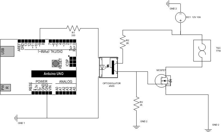
I want to switch a Thermoelectric Peltier Cooler (TEC1-12705) (12V - 77 Watts) using an Uno. I am an engineer but not an EE so I could use some guidance on circuit setup. There was a very good discussion on the page below but I need a bit more assistance on R values etc..

How to drive a MOSFET with an optocoupler?

I have the following:

  1. optocoupler - 4N35
  2. MOSFET - N-Channel MOSFET 60V 30A

Here is my circuit:

enter image description here

\$\endgroup\$
2
  • \$\begingroup\$ What is the problem? R1 looks good assuming the drop across the LED is sufficient to not draw too much current from the pins. The way you have it right now means that the MOSFET will be normalling conducting since R3 will act as a pull-down resistor when the 4N35 is off. Also there is no current-limiting resistor, so the current will be limited only by the on-state resistance of the mostfet and whatever the TEC's load is. \$\endgroup\$
    – sherrellbc
    Commented Jul 25, 2014 at 19:42
  • \$\begingroup\$ As it happens, the subject was pretty thoroughly answered in electronics.stackexchange.com/questions/118536/… \$\endgroup\$ Commented Jul 25, 2014 at 22:43

2 Answers 2

1
\$\begingroup\$

I don't see any reason why your schematic wouldn't work as is. I've never used an optocoupler like yours, but here's a breakdown of what I looked at.

Is the input current safe for the optocoupler and the arduino?...

  • Diode_Imax: 50mA
  • Diode_Von: 1.2V
  • Diode_Ion: 10mA
  • Arduino_Imax: ~35mA?
  • Arduino_Vpin: 5V

$$I\_diode = \frac{Arduino\_V{pin}-Diode\_V{on}}{R1}$$ $$I\_diode = \frac{5V-1.2V}{330\Omega} = 11.5mA$$ $$Diode\_Ion < I\_diode < Diode\_Imax ... Good$$ $$I\_diode < Arduino\_Imax ... (Good)$$

Is the current through the optocoupler BJT a safe value?...

  • BJT Ice_max: 50mA

$$Ice = \frac{V_{supply}}{R2+R3}$$ $$Ice = \frac{12V}{2k\Omega+2k\Omega} = 3mA$$ $$Ice < Ice_{max} ... (Good)$$

Will the voltage divider formed by R2 & R3 turn the FET ON?...

  • Von: 5V

$$Vgs = V{supply} \cdot \frac{R2}{R1+R2}$$ $$Vgs = 12V*(2kohm/(2kohm+2kohm)) = 6V$$ $$Vgs > Von ... (Good)$$

Is the final output safe for the FET, peltier, and power supply?...

  • Supply_Imax: 10A
  • Peltier_Imax: 5.3A
  • Peltier_Vmax: 14.2V
  • Peltier_R: 2.4 ohms
  • FET_IDmax: 22.6A
  • FET_Ron: < 0.1 ohm (ignored)

$$I{supply} = \frac{V{supply}}{Peltier\_R} $$ $$I{supply} = \frac{12V}{2.4ohm} = 5A $$ $$I{supply} < Supply\_I{max} ... (Good) $$ $$I{supply} < FET\_ID{max} ... (Good) $$ $$I{supply} < Peltier\_I{max} ... (Close) $$

The current through the peltier is close to its max limit. Is that a problem? I don't know. The max rating could already be derated and there could be variation in the peltier resistance or the supply voltage. Personally, I would probably add a 1-2ohm power resistor, but that would waste power to give myself piece of mind. Another option would be to increase Ron, by decreasing R3 or using a less efficient FET.
\$\endgroup\$
2
  • \$\begingroup\$ Thank you very much for this post. In another post one person said that this circuit would be on all the time unless the Arduino pin was set to high (5V) then it would be off. I dont see that situation - Arduino pin controls the opto and it is open circuit if there is no diode voltage. \$\endgroup\$
    – user50109
    Commented Jul 28, 2014 at 17:57
  • \$\begingroup\$ @user50109 I agree. R3 acts as a pull-down resistor, turning the FET off. It would be easy to test. Hook up the circuit without the FET or the peltier. Pulse the arduino pin and the voltage at the top of R3 should change from 6V to 0V. \$\endgroup\$
    – curtis
    Commented Jul 31, 2014 at 21:51
0
\$\begingroup\$

The resistor values have the following requirements:

R1 limits the current into the optoisolater. Look at the datasheet for that part. Find the forward voltage of the LED (Vf) and an appropriate current to turn it on (Ion). If your arduino IO voltage is Vio then you want R1 such that:

(Vio-Vf)/R1 = Ion

Make sure the arduino IO can handle that current, as well.

R2 and R3 form a divider to drive the gate of the FET. The gate voltage when the FET is on (assuming small Rdson of the FET) is 12V*R3/(R3+R2). This voltage should be enough to turn on the FET but not so much as to over-voltage it's gate. It seems to me that you could do without R2 since the FET is rated for > 12V...

\$\endgroup\$
1
  • \$\begingroup\$ Thank you for the explanation of all the components of this circuit. Wonderful to have the help. \$\endgroup\$
    – user50109
    Commented Jul 28, 2014 at 17:58

Your Answer

By clicking “Post Your Answer”, you agree to our terms of service and acknowledge you have read our privacy policy.

Not the answer you're looking for? Browse other questions tagged or ask your own question.