0
\$\begingroup\$

Sorry I'm sure this is a very simple answer but I know very little about how it works beyond serial ports and USB adapters for interacting with PCB circuits.

I've taken apart an old junk flip camcorder, which runs various programs etc. and would like to program it to display whatever such as C code or reconfigure what the play button does. I've been able to locate the microprocessor and searched its datasheet but I still cannot find out how to connect it to my computer by any means. Beyond that and the large chips, I have no idea where to look.

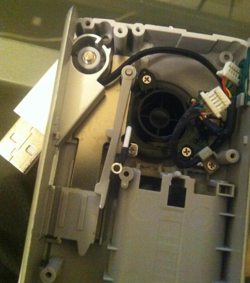
Here is the device itself: see below photo please
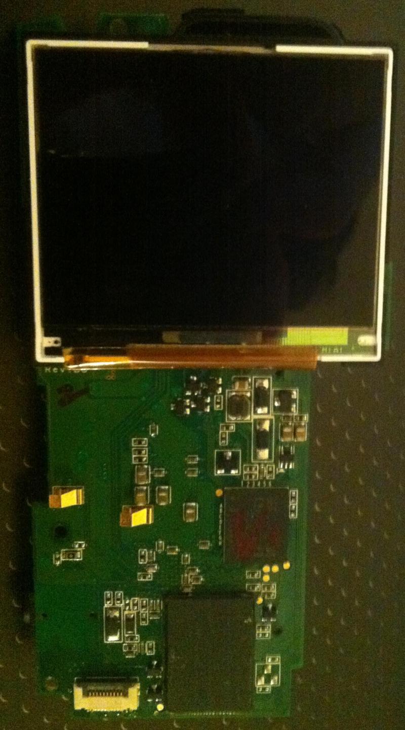
Flip Device

And the USB connection:

Flip USB Connection

I can plug the USB into the PC but the issue is camera is buggy and doesn't register as a USB device (otherwise I'd just reformat it) so that's why I was trying to connect to the board itself and not mess with the USB. I know the device works because the load screen shows and a red light appears with only the USB attached. Any ideas?

https://i.sstatic.net/xfhFk.jpg <-sorry! this is the picture with all the active connections, the other side does not have much

edit: ive got it to appear on the computer somehow, and can read all the .nib files with the variables etc. If say the usb was broken or something else the next way to go about it would be the JTAG as everyone is saying?

\$\endgroup\$
3
  • \$\begingroup\$ Please add the part number for the microcontroller, and link to its data sheet to your question. Without the part number it is difficult to give accurate advice. If you can, it might help to give close-ups of the large chips so folks can read the ID information. \$\endgroup\$
    – gbulmer
    Commented Aug 23, 2014 at 10:52
  • \$\begingroup\$ The round gold circle pads are probably a jtag interface or similar. \$\endgroup\$ Commented Aug 23, 2014 at 15:31
  • \$\begingroup\$ Trying to program a commercial product, from scratch and without engineering documentation, is a monumental task that frankly, you cannot do based on your question. \$\endgroup\$
    – Passerby
    Commented Aug 24, 2014 at 0:28

3 Answers 3

2
\$\begingroup\$

There is no guarantee that the manufacturer put any way to program the MCU onto the PCB.

MCU's could be programmed before assembly.

It may be infeasible to program the MCU even if you could get at the right pins. Most MCU's have built-in mechanisms to allow a user (in this case camera manufacturer) to prevent a chip being reprogrammed, or the program read. It is likely that the camera manufacturer used those mechanisms.

It is sometimes possible to defeat those mechanisms, but those forms of 'attack' may damage the chip, and make it unusable.

\$\endgroup\$
0
\$\begingroup\$

You will have to find a JTAG adapter suitable for this MCU, and, obviously, the relevant JTAG connection on the PCB. Most consumer products cannot be programmed or debugged through the USB connection.

\$\endgroup\$
1
  • 1
    \$\begingroup\$ To add to this, those things were made in enormous volume, so they may not even have JTAG ports, but rather just have pre-programmed flash soldered down to the board. Alternatively, the little gold pads visible may have been for a bed-of-nails programming interface. \$\endgroup\$ Commented Aug 23, 2014 at 9:03
0
\$\begingroup\$

I could be wrong, but I strongly suspect that your better use of the device is as a parts supply - scavenge the display & learn how to hardware-hack it, scavenge the button switches, maybe grab a few other internal parts if they look handy.

\$\endgroup\$

Your Answer

By clicking “Post Your Answer”, you agree to our terms of service and acknowledge you have read our privacy policy.

Not the answer you're looking for? Browse other questions tagged or ask your own question.