I want to use optical encoder in my design.
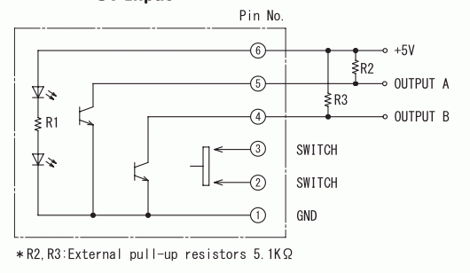
In the datasheet of the optical encoder, pin2 and pin3 are used as switches.
Could you please explain how these switches work and how to use them?
I want to use optical encoder in my design.
In the datasheet of the optical encoder, pin2 and pin3 are used as switches.
Could you please explain how these switches work and how to use them?
Pins 2 and 3 are the contacts of a SPST normally-open momentary pushbutton switch, and are often used to select a menu item presented as a line of alpha or numeric data on a character LCD.
For instance, assume you had a bench supply with an output variable from zero to 10 volts in one volt steps, with the steps switched through and presented on the LCD when the rotary encoder was turned. Then, once the proper voltage was selected, the pushbutton would be pressed to turn the output on and display "OUTPUT ON" or suchlike, and then pressed again to turn the output off and display "OUTPUT OFF".

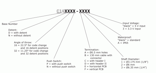
Pin2 and pin3 are the two contacts of the push-to-close switch. If you don't want to use that feature you can leave them unconnected. Or you can buy the version without the switch, the numbering explanation suggests that such version exists:
