No, it's not correct, if only because neither the LED nor the power supply are 3.3V. The power supply may be 3.28V, and the LED voltage 3.32V, and then the simple calculation for the series resistor doesn't hold anymore.
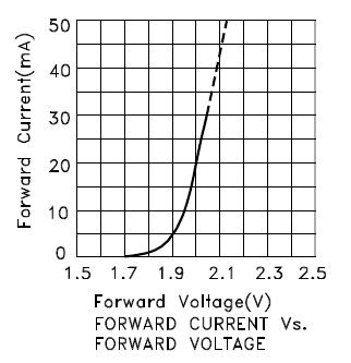
The model of a LED is not just a constant voltage drop, but rather a constant voltage in series with a resistor, the internal resistance. Since I don't have the data for your LED let's look at this characteristic for another LED, the Kingbright KP-2012EC LED:

For currents higher than 10mA the curve is straight, and the slope is the inverse of the internal resistance. At 20mA the forward voltage is 2V, at 10mA this is 1.95V. Then the internal resistance is
\$R_{INT} = \dfrac{V_1 - V_2}{I_1 - I_2} = \dfrac{2V - 1.95V}{20mA - 10mA} = 5\Omega\$.
The intrinsic voltage is
\$V_{INT} = V_1 - I_1 \times R_{INT} = 2V - 20mA \times 5\Omega = 1.9V.\$
Suppose we have a power supply of 2V, then the problem looks a bit like the original, where we had 3.3V for both supply and LED.
If we would connect the LED through a 0\$\Omega\$ resistor (both voltages are equal after all!) we get a LED current of 20mA. If the power supply voltage would change to 2.05V, just a 50mV rise, then the LED current would be
\$ I_{LED} = \dfrac{2.05V - 1.9V}{5\Omega} = 30mA.\$
So a small change in voltage will result in a large change in current. This shows in the steepness of the graph, and the low internal resistance. That's why you need an external resistance which is much higher, so that we have the current better under control. Of course, a voltage drop of 10mV over, say, 100\$\Omega\$ gives only 100\$\mu\$A, which will be hardly visible. Therefore also a higher voltage difference is required.
You always need a sufficiently large voltage drop over the resistor to have a more or less constant LED current.

