2
\$\begingroup\$

I'm working with 6 LEDs in series, which are rated at:

  • 3V Typical / 3.2V Maximum
  • 20mA.

My power supply is:

  • 19V
  • 3A Maximum

According to my calculations:

  • I'd need a 50 ohm resistor at 3V
  • I'd be in the negative at 3.2V.

Because my target resistance with the LEDs alone would be below the maximum LED voltage specification, do I need any sort of resistor at all?

Is this the appropriate use case for a 0 ohm resistor?

I plugged in the array last night for around 20 seconds or so, and the wiring seemed to get rather hot which is a bit worrisome... The LEDs however, didn't appear to be brighter than when connecting one at the appropriate resistance.

\$\endgroup\$
3
  • 3
    \$\begingroup\$ See electronics.stackexchange.com/questions/12865/… ; hot wiring does not sound good! \$\endgroup\$
    – pjc50
    Commented Nov 14, 2013 at 18:32
  • \$\begingroup\$ The LEDs are rated at 3V, So the calculations should be done by rating value. witch as you calculated is 50ohm. \$\endgroup\$ Commented Nov 14, 2013 at 19:25
  • \$\begingroup\$ Just a little note. 0 Ohm resistors are really only used for making circuits or PCBs. If you need to jump over a track on a PCB instead of having a bit of wire hanging on the board a 0 Ohm resistor acts as a little bridge. Its easier for the machines to pick up and place and solder than to pick up a piece of wire. In all other case such as at home you WOULD just use some wire :) \$\endgroup\$ Commented Nov 14, 2013 at 23:18

2 Answers 2

9
\$\begingroup\$

LEDs are diodes, so over the normal operating range the voltage is relatively stable for wide ranges in current. However, this also means that if you were to drive a LED with voltage, small changes in that voltage will cause large changes in the current. The characteristics are not definite enough to make this current predictable. LEDs therefore need to be driven with a controlled current, not with a low impedance supply.

Your basic flaw is that you are trying to drive too many LEDs in series for the voltage you have. Get a higher voltage supply, lower voltage LEDs, or put fewer of them in each series string. With 5 LEDs in a series string, the nominal drop will be 15 V. That leaves 4 V for a resistor to drop, which is good since that will reduce current variations as the LED voltages vary. 4 V / 20 mA = 200 Ω, which is the size resistor you should use with 5 LEDs in series driven from a 19 V supply.

\$\endgroup\$
4
  • \$\begingroup\$ Your explanation and logic makes perfect sense, and absolutely answers my question. Thank you so much for the response, and concise examples. \$\endgroup\$ Commented Nov 14, 2013 at 19:50
  • \$\begingroup\$ the only thing you have to check is if at 20mA the diode voltage drop is 3 V if it is not you have to recalculate. \$\endgroup\$ Commented Nov 15, 2013 at 0:02
  • \$\begingroup\$ @INGJ: No, you don't have to "check". The manufacturer has already done this and given you the answer. Even better, they give you some idea of the range to expect, which is something a single measurement won't tell you. If you use 200 Ohms, the current will be 20 mA at nominal voltage. If the LEDs are actually at the maximum of 3.2 V, then the current will drop to 15 mA, which is not a big change in apparent brightness. If you want better regulation, use a current source instead of a resistor. With 4 V, there is sufficient room for a current source or sink. \$\endgroup\$ Commented Nov 15, 2013 at 13:38
  • \$\begingroup\$ Dear @OlinLathrop if u had the oportunity to check my first explanation you will understand that I recomended him to check the datasheet...(first)... and I said "if you have not the datasheet or you dont know the part number you can calculate the voltage at rated current" (second)... and finally in a series circuit the current do not drop... is equals y all the elements... at least you have been using a current source in the middle of the series circuit wich is not the case. \$\endgroup\$ Commented Nov 16, 2013 at 1:35
2
\$\begingroup\$

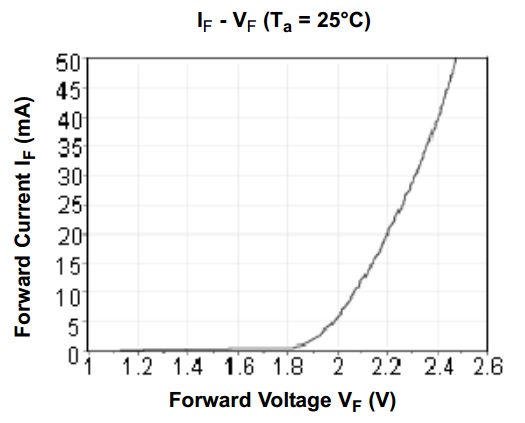
If you want your LED works at 20mA of course you have to put a resistor. But I would like you to provide the right voltage of the diode at 20mA because the voltage of te diode is different at diferent current rate.

see the image...

enter image description here

As you can see in the image the led voltage at 20mA is 2.2 volts...

for the right resistor you can use the next formula that I calculate for you.

R=-(6*Vd-Vs)/Id

where R is the resistor you have to use, Vd is the diode voltage at desired current rate (20mA) Vs is the source voltage and Id is the current operation (20mA)

The number 6 in the formula is because you are using 6 series leds...

If you do not know the voltage in the led at 20mA... you can use a potentiometer in series with one led, measure the current and the voltage in the diode, when you measure 20mA in the multimeter, then the voltage in the diode is the voltage at 20mA and you can use this value for the formula that I provide

\$\endgroup\$
1
  • \$\begingroup\$ Using a potentiometer within the circuit is actually quite brilliant for determining the voltage at a specific current, thanks for the suggestion. \$\endgroup\$ Commented Nov 14, 2013 at 19:54

Not the answer you're looking for? Browse other questions tagged or ask your own question.