0
\$\begingroup\$

I don´t get to get the bitstream file. I have several errors when I try to generate the bitstream file. The error
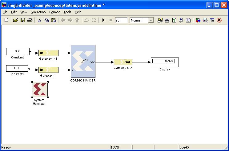
I have this error message from the file called xflow.results:

ERROR:Par:228 - At least one timing constraint is impossible to meet because component delays alone exceed the constraint. A physical timing constraint summary follows. This summary will show a MINIMUM net delay for the paths. The "Actual" delays listed in this summary are the UNROUTED delays with a 100 ps timing budget for each route, NOT the achieved timing. Any constraint in the summary showing a failure ("*" in the first column) has a constraint that is too tight. These constraints must be relaxed before PAR can continue.

Please use the Timing Analyzer (GUI) or TRCE (command line) with the Mapped NCD and PCF files to identify the problem paths. For more information about the Timing Analyzer, consult the Xilinx Timing Analyzer Reference manual; for more information on TRCE, consult the Xilinx Development System Reference Guide "TRACE" chapter.

This is strange to me because I have never had a constraint problem before.

What could I do to avoid constraint problems in System Generator?

The link for my .mdl file: https://www.dropbox.com/s/h15ns3p55wlbuc2/singledivider_exampleconceptlatencyandsimtime.mdl

The link for my xflow. file: https://www.dropbox.com/s/odqoakbrs21ngbx/xflow.results

\$\endgroup\$
2
  • \$\begingroup\$ The xflow.results you have linked doesn't seem to match the question. \$\endgroup\$
    – Andy
    Commented Apr 15, 2011 at 15:44
  • \$\begingroup\$ I´ve just changed it. \$\endgroup\$
    – Peterstone
    Commented Apr 16, 2011 at 5:34

1 Answer 1

2
\$\begingroup\$

The error means that your design can not run as fast as you are telling the tools it needs to. There are a few possible strategies:

  1. If you are doing this as an experiment without specific requirements, you could try a smaller divider, that is more likely to work at the clock frequency you have.

  2. If your board allows you to select a different clock frequency for the FPGA, you can do that, and update the constraints with the lower frequency.

  3. You can add registers to your design to reduce the length of the critical path, as described here.

  4. You can add a clock divider to your design. There is an example in Pipelining and clock frequency issue.

\$\endgroup\$
1
  • \$\begingroup\$ I changed the time constraints, by putting the different clock frequency and It´s works. \$\endgroup\$
    – Peterstone
    Commented Jun 4, 2011 at 5:39

Your Answer

By clicking “Post Your Answer”, you agree to our terms of service and acknowledge you have read our privacy policy.

Not the answer you're looking for? Browse other questions tagged or ask your own question.