When we connect a resistor to current source a finite amount of current flows through it right? Okay but how is a closed path complete?I mean the current source has infinite resistance(I'm talking about ideal) so no current flows thorough it.it's like the circuit is open right?
3 Answers
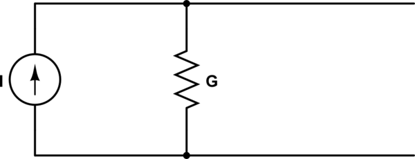
When we say an ideal current source has infinite resistance, we are not talking about series resistance, we are talking about shunting resistance. The model of a non-ideal current source looks like this:

simulate this circuit – Schematic created using CircuitLab
In this diagram I labelled the resistor as "G" instead of "R" to emphasize that this is the dual of a voltage source, so it has a shunt conductor instead of a series resistor.
When we say an ideal current source has infinite resistance, we really should say it has 0 conductance, the dual of the ideal voltage source having 0 resistance.
If we add a load resistor we have this circuit:

And indeed, even if G is 0, there is a complete circuit. Current flows through the ideal current source, through the load, and back through the connection to the other terminal of the source.
If you are concerned that current can't flow through the current source because of Ohm's law, remember that Ohm's law isn't a law for all circuit elements, it's just a description of one type of element: the resistor. Current can also flow through other elements that have nothing to do with Ohm's law like capacitors, inductors, and sources.
Edit
This is to explain what I mean about circuit duality and why I bring it up.
First, in circuit theory neither the voltage source nor the current source is more fundamental than the other. Understanding both is necessary in order to model all circuits. For example, when doing transient analysis of circuits containing capacitors and inductors, the model of the capacitor at each timestep contains an ideal voltage source and the model of an inductor at each timestep contains an ideal current source. Even among practical circuits there are sources that are more straightforward to model as current sources than voltage sources: current mirrors and certain switching power supply configurations come to mind. We also use current sources to model the collector-emitter branch of a BJT in many cases.
Now, how does duality apply to this question?
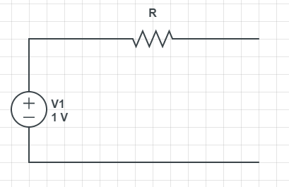
You are probably already familiar with the voltage source, which looks like this:

And this model leads you to ask, if an ideal current source has infinite resistance, how can any current at all flow through it?
What you are missing is that when you talk about current sources, you are talking about the dual of the voltage source. And when you convert to the dual, you should convert series resistance to shunt conductance. This gives the current source model I showed above:

Notice that I didn't just replace the resistor with a conductor. I changed the circuit topology from series to parallel.
As you can see, in this dual device, when G goes to 0 (when the internal resistance is infinite) it does nothing at all to prevent current flowing through the source. It simply allows the ideal current source to deliver all of its value to the load, rather than having some shunted by its non-ideality element.
Just like how, by duality, in the voltage source when the non-ideality element (resistor) goes to 0, it allows all of the voltage to be delivered to the load.
-
\$\begingroup\$ I'm not convinced. Your circuit is only the equivalent of a voltage source with a series resistor. When you set G to zero, then the current through a normal RL would be very low. That RL can see a constant current, independet of it's own value, G should have infinite resistance. And additionally in your circuit I is still an unexplained constant current source. An ideal current source can only be described with an infinite voltage source and an infinite resistor, but then the current is undefined. In reality you have to talk about active regulation and differential resistance. \$\endgroup\$– KitanaCommented Nov 23, 2014 at 22:06
-
\$\begingroup\$ I agree with @kitana - you are describing a current source with less than ideal quality. You aren't describing a current source in terms of a voltage source in series with a resistor. \$\endgroup\$– Andy akaCommented Nov 23, 2014 at 22:34
-
\$\begingroup\$ @Kitana, Nothing makes a voltage source more fundamental than a current source. You say, "An ideal current source can only be described with an infinite voltage source and an infinite resistor". I could equivalently say an ideal voltage source can only be described with an infinite current source and an infinite conductance. In fact, either one can be described with a single equation: either "V = Vs" or "I = Is". \$\endgroup\$ Commented Nov 23, 2014 at 22:34
-
\$\begingroup\$ @Andyaka, who says a current source has to be described as a voltage source with a series resistor? A current source and a voltage source are duals of each other. Neither one is necessarily constructed from the other one. \$\endgroup\$ Commented Nov 23, 2014 at 22:35
-
\$\begingroup\$ First off big thanks for the answers. But I too am not salsified with the explanation. An ideal current source is dual of ideal voltage source. Since voltage source has zero series resistance current source should have zero shunt resistance so....... \$\endgroup\$ Commented Nov 24, 2014 at 3:20
A perfect theoretical current source will drive it's current through an open circuit (if necessary) by self-adjusting the voltage at its output terminals to create thousands or millions of volts. Of course, in practise this is nonesense but who's talking about the real world?
This is why a theoretical current source is an infinite voltage divided by an infinite resistance (with the ratio of that infinite voltage to that infinite resistance being equal to the current it always supplies at its terminals).
It's not practical so don't lose sleep about it!
The internal resistance of a source can be determined by making two measurements. The voltage without any load and the short-circuit current. Dividing the two one gets the internal resistance. $$ R_{i} = \frac {U_{s}}{I_{s}} $$ In real life it's often not advisable the make a short circuit, instead one makes the measurement with two different resistors and determines the change of the voltage and the current. $$ r_{i} = \frac {\Delta U}{\Delta I} $$ The lowercase "r" indicates that it's a so called differential resistance. This differential resitance must no be the same over the whole operating range. Especially in extreme cases it will change.
With an ideal voltage source the voltage wouldn't change at all. \$\Delta U\$ and thus \$r_{i}\$ would be zero. Contrary an ideal current source would show no current change at all. Putting \$\Delta I = 0\$ in the formula above would give an error. \$r_{i}\$ is undefinded. Now there's a mathematical workaround for this problem, the "limit of a function". We make \$\Delta I\$ step by step smaller and look what happens with \$r_{i}\$. It becomes higher and higher, moving towards infinity. $$ r_{i} = \lim_{\Delta I \to 0} \frac {\Delta U}{\Delta I} = \infty $$ Now we know why it's said that an ideal current source has infinite resistance.
In reality there are no ideal sources, infinite voltages or infinite currents, but the concept of an ideal source is very helpfull for calculations.
With modern electronics and active regulation, it's possible to build power supplies that come very close to these ideals - within determined boundaries. Real power supplies have a maximum for the voltage and the current that they can deliver. Below these limits they make a real good job.
-
\$\begingroup\$ If we transform an ideal voltage source to current source it has 0 resistance in parallel to it. Which means no current flows through a resistance connected across the current source ( since current prefers less resistance path and 0 is the shortest resistance ). So what is happening here no current flows through a resistor connected across an 'IDEAL' current source. The less ideal it gets more is it's functionality. \$\endgroup\$ Commented Nov 24, 2014 at 14:22
-
\$\begingroup\$ @dushyanth - Making the transformation you would get a current source with infinite current. Can someone then calculate the current through the load resistor? Once more it's obvious that such transformations applied on ideal sources make no sense. The use of ideal sources lies in modelling real sources, with real internal resistances, then you can apply those transformations. \$\endgroup\$– KitanaCommented Nov 24, 2014 at 15:02
