2
\$\begingroup\$

When I google things like voltage source and current source they talk about things like maintaining a particular level, having infinite output resistance, or zero output resistance, etc. I don't understand what this means at all or why it must necessarily follow, and none of the online explanations actually get into why these things are the case. If something has infinite resistance wouldn't nothing happen because everything is blocked?

I also don't understand what an "open circuit" really means (to my eye it just looks like a broken circuit that isn't going to do anything). It's all quite horribly confusing to me and all the online guides and answers just repeat the same stuff. Can anyone explain this to me like I am a dummy?

\$\endgroup\$
3
  • 5
    \$\begingroup\$ I think you're trying to tackle too many new concepts at the same time. \$\endgroup\$
    – DKNguyen
    Commented Oct 4, 2020 at 5:16
  • 1
    \$\begingroup\$ ^^^ Agree - You gotta start with the basics. First you master Ohms Law. Then you master resistor circuit analysis (things like parallel & series). And you HAVE to do the MATH all along the way ... Electricity is not intuitive, you can't jump in like you may be able to with mechanics. Don't feel bad, it took humanity until about 1865 to get as far as you have. In the early 1800's we had steamships sailing across the oceans, but we were still using severed frog legs as 'voltmeters'. This stuff is complicated. You take it off in little bits, not big chunks, and you'll get there. \$\endgroup\$
    – Kyle B
    Commented Oct 4, 2020 at 6:12
  • \$\begingroup\$ @user525966, An excellent question that deeply impressed me... and made me once again think deeply about the essence of these concepts... I will try to answer you as simple as possible so that even if it becomes clear to me:) But while I am assembling my answer, I ask you to take a look at the question and my answer about the philosophy behind the implementation of circuit current sources - electronics.stackexchange.com/questions/479081/…. I know it won't be that easy for you but let's try... \$\endgroup\$ Commented Oct 4, 2020 at 17:38

5 Answers 5

13
\$\begingroup\$

If something has infinite resistance wouldn't nothing happen because everything is blocked?

I also don't understand what an "open circuit" really means (to my eye it just looks like a broken circuit that isn't going to do anything). It's all quite horribly confusing to me and all the online guides and answers just repeat the same stuff. Can anyone explain this to me like I am a dummy?

You are getting confused because you are thinking that voltage flows.

Current flows, but voltage does not flow. This means you can block a current so that the current flow is zero. But you can't block voltage, not because voltage is unblockable, but because it doesn't make sense to talk about blocking it since it doesn't flow in the first place.

It is like how you can block a ball from falling off a table, but you can't block it from having \$E=mgh\$ of potential energy while sitting on that table.

I also don't understand what an "open circuit" really means (to my eye it just looks like a broken circuit that isn't going to do anything).
schematic

simulate this circuit – Schematic created using CircuitLab

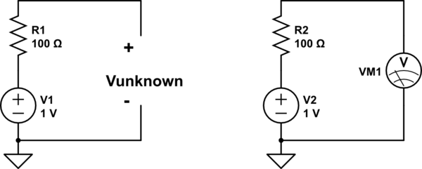
What is the current flow in the circuit on the left? It's an open-circuit which means the circuit path is broken and not closed which means no current can flow. Agreed?

If no current can flow, what is the voltage drop across R1? \$V_{R1} = IR_{1} = 0amps \times 100 \Omega = 0V\$ Agreed?

So if the voltage drop across R1 is 0V, what is the voltage \$V_{unknown}\$? It is V1 because V1 has a voltage of 1V, but R1 has a voltage drop of 0V.

The circuit on the right is the same except we have connected a voltmeter VM1 where \$V_{unknown}\$ is so we can actually measure it. The voltmeter is designed to allow no current to flow through it so the circuit on the right is no different from the circuit on the right. In other words, the voltmeter VM1 can be thought of as an infinite Ohm resistor as far as the circuit is concerned.

Don't even worry about output resistance (and more generally, impedance) of voltage or current sources until you understand the above.


schematic

simulate this circuit

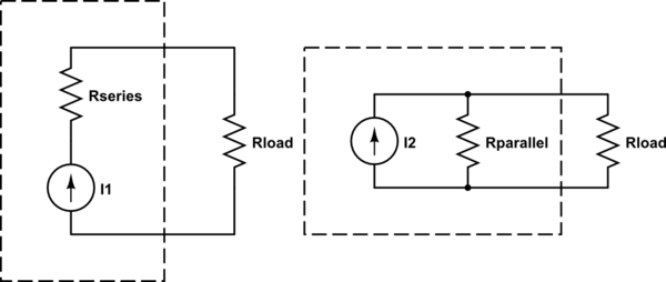
These are a non-ideal voltage source and a current source with output resistance. Everything inside the dotted box is part of the non-ideal source.

For the non-ideal voltage source, \$R_{parallel}\$ cannot influence the voltage that the ideal voltage source applies to \$R_{load}\$. The ideal voltage source simply applies its ideal voltage to both \$R_{parallel}\$ and \$R_{load}\$. So we do not talk about internal parallel resistances as an output resistance for a voltage source.

But it should be obvious that \$R_{series}\$ can interfere with the voltage that the ideal voltage source is trying to apply to \$R_{load}\$, and the voltage that \$R_{load}\$ actually gets. If current flows, then some voltage will be lost across \$R_{series}\$ and change the voltage seen by \$R_{load}\$. The more current that it needs to supply, the more the voltage drops below ideal. So when we talk about the output impedance for a voltage source, we are talking about a series resistance.

schematic

simulate this circuit

For the current source, \$R_{series}\$ cannot influence the output current. It cannot affect the current running through \$R_{load}\$. The ideal current source simply drives whatever current it wants to drive and it goes through both \$R_{series}\$ and \$R_{load}\$. Therefore, we do not talk about series resistances as an output resistance for current sources.

But it should be obvious that \$R_{parallel}\$ can disrupt the current that the ideal current source is trying to push through \$R_{load}\$, and the current that actually flows through \$R_{load}\$. Since the current source outputs a fixed amount of current, some current will be split between \$R_{series}\$ and \$R_{load}\$. That means that as more current is supplied, less and less current reaches \$R_{load}\$. So when we talk about an output resistance for a current source, we are talking about an internal parallel resistance.


Now...what do they mean when they say an IDEAL voltage source has zero output impedance and an IDEAL current source has infinite output impedance? Look at the circuits for V1 and I2.

What does \$R_{series}\$ have to make the circuit for V1 into an ideal voltage source? It needs \$R_{series} = 0 \Omega \$, ergo ideal voltage sources have zero output resistance.

What does \$R_{parallel}\$ have to make the circuit for I2 into an ideal current source? It needs \$R_{parallel} = \infty \Omega \$, ergo ideal voltage sources have zero output resistance.

If something has infinite resistance wouldn't nothing happen because everything is blocked?

So by now, you should have realized that the output resistance for a current source is considered to be in parallel, not in series like it would be for a voltage source. If this parallel resistance is infinite it doesn't block any output current from reach the load, rather it stops output current from leaking away before it reaches the load.

\$\endgroup\$
15
  • \$\begingroup\$ I'm actually talking about the opposite ("An ideal current source has infinite output impedance"), the idea that a current source has infinite resistance, which confuses me because I think of current as flowing, as infinite resistance blocks all flow. I don't think of voltage as something that flows, just a difference in energy levels / a "pressure" \$\endgroup\$
    – user525966
    Commented Oct 4, 2020 at 5:48
  • \$\begingroup\$ @user525966 Well, just look at the schematic for the non-ideal current source I2 which has an output impedance. For current sources, the output impedance is considered to be in parallel with the ideal source (as explained in the answer). Now, what Rparallel, have to be to make it become an ideal current source? It has to be infinite, right? Similarly, voltage source V1 needs Rseries to be equal to zero, right? Ergo, ideal current sources have infinite output resistance and ideal voltage sources have zero output resistance. \$\endgroup\$
    – DKNguyen
    Commented Oct 4, 2020 at 5:52
  • 2
    \$\begingroup\$ So an ideal voltage source has no output impedance (because otherwise we'd have a resistance causing a voltage drop, which means we deliver less voltage than we wanted to the load) and it's assumed we're talking series resistance? And an ideal current source has infinite output impedance (so that there is no other pathway for current to go - it must all go towards the load), and it's assumed we're talking about parallel resistance? Am I understanding you? \$\endgroup\$
    – user525966
    Commented Oct 4, 2020 at 6:08
  • 2
    \$\begingroup\$ @DKNguyen, I often enjoy your explanations and like them... but not now. Honestly, if I had to understand these simple electrical concepts from your explanations above, this would not happen. They are true and correct... but do not explain the simple truth. I am sorry... but I had to tell you... because I respect you... \$\endgroup\$ Commented Oct 4, 2020 at 10:03
  • 1
    \$\begingroup\$ DKNguyen, you are correct: "it doesn`t have to be". Therefore, I wrote"...always a static resistor ?". Because - very often in electronics it is a dynamic resistance...(example: rce for a BJT) \$\endgroup\$
    – LvW
    Commented Oct 7, 2020 at 13:51
1
\$\begingroup\$

It's a crying shame that so many sources repeat the same unhelpful mantra.

In reality there are no ideal voltage or current sources. They're simply a tool to aid circuit analysis.

The closest you're likely to get to a true voltage source is a large lead acid battery or maybe even Li-ion. It'll maintain it's ability to force current (using its voltage) through your load almost no matter what ! Of course it fails to do so because in the real world there is resistance in the way, no matter how low.

You can of course use feedback in a circuit to generate artificially ultra low resistances, even to the extent of negative resistance but that's cheating !

Here's the thing. Electricity can be considered as somewhat comparable to water flow. Voltage is analogous to pressure and current is analogous to errr ... current (rate of flow).

In the same way that pressure forces water through pipes, voltage forces current through a wire or load.

The 'ideal' current source is simply a theoretical concept that can 'force' the current in question through a load, no matter what. It can't exist in practice since it would need infinite voltage to work.

\$\endgroup\$
3
  • \$\begingroup\$ Of course there are current sources "in practice", just as there are voltage sources. Perhaps you forgot the word "ideal" in your last paragraph. \$\endgroup\$ Commented Oct 8, 2020 at 20:15
  • \$\begingroup\$ You may have missed 'In reality there are no ideal voltage or current sources' but I'll add 'ideal' in my last sentence, I couldn't find 'in practice' in my text. \$\endgroup\$ Commented Oct 8, 2020 at 20:28
  • \$\begingroup\$ Count ten words back from the very end. While you may have spoken clearly in an early part of your answer, I think it helps the newcomers if the language is consistent throughout. Thanks for fixing that last paragraph. \$\endgroup\$ Commented Oct 8, 2020 at 22:16
0
\$\begingroup\$

After examining some schematics, proceed to examine LOAD_LINES.

A I_versus_V plot, with I the vertical axis, is very helpful.

A flat load line (horizontal line) provides an infinite compliance and infinite Rload part of the graph.

A vertical load line provides a short circuit indicator.

As Rene deCartes firmly suggested in his 4 steps to understanding, the more methods to understanding we bring to bear on a concept, the more likely we'll uncover the underlying principles.

Hence I suggest pondering load_lines.

\$\endgroup\$
2
  • \$\begingroup\$ Please make some (even small) edits to unlock my vote so I can correct it (I accidentally pressed the downvote button). \$\endgroup\$ Commented Oct 6, 2020 at 5:32
  • \$\begingroup\$ OK, i have corrected my vote. BTW I think that "load line" is not the most appropriate word in the case. It is more like "generator line" or best "IV curve of the source" (including the resistance). As you can see, I also try to use as many points of view as possible to explain circuit phenomena. \$\endgroup\$ Commented Oct 6, 2020 at 14:43
0
\$\begingroup\$

Just a short note on "current sources":

  • In reality, there are no real current sources. Each current needs a driving voltage (this applies even to photo-sensitive parts). Hence, the known symbol for a current source with a parallel (static, ohmic) source resistor is nothing else than an equivalent description of a voltage source with a series source resistor.

  • The term "current source" is - more or less - "labour jargon" and is used to describe a voltage source with a very large source resistance (example: Output resistance of a BJT: 1/h22, rce). So - when discussing source resistances, it is very important to discriminate betwen static (ohmic) and dynamic (differential) resistances.Therefore, the BJT is nothing else tha a - non-ideal - voltage-driven current source (VCCS). However, very often it is treated as an ideal current source (rce=1/h22 infinite).

  • So - what does it mean when we speak about an "ideal" current source? Infinite source resistance? YES - but only an infinite differential source resistance. Hence, this source can, of course, supply a certain current which is insensitive to load changes.

\$\endgroup\$
12
  • \$\begingroup\$ A current source the same as a voltage source with resistor? I don't understand that part \$\endgroup\$
    – user525966
    Commented Oct 7, 2020 at 13:31
  • \$\begingroup\$ A voltage source with a source resistor Rs>>Rload is "called" current source (because Rs mainly determines the current through the load.) But this is only something like "labour jargon" because - in reality - there is no current source at all. Each current needs a voltage source as a driving power! \$\endgroup\$
    – LvW
    Commented Oct 7, 2020 at 13:48
  • \$\begingroup\$ So a "real life" source of current can be thought of as an ideal current source with some parallel resistance right? But then an ideal current source can be thought of as a voltage source with another resistor in series? Is that correct? (so a real life current source is sort of like a voltage source with two resistors arranged a certain way, which can be simplified then to a single resistor)? \$\endgroup\$
    – user525966
    Commented Oct 7, 2020 at 14:53
  • 1
    \$\begingroup\$ Yes - but in reality there is no IDEAL current source..it is a model only ! \$\endgroup\$
    – LvW
    Commented Oct 7, 2020 at 16:39
  • 1
    \$\begingroup\$ Where is the problem? A current needs an E-field within the wire or resistor. Otherwise, there is no force to cause a movement of the electrons. Such an E-field can be produced by a voltage onlky! Hence, the primary source must be a voltage source! And the current is the result. There is no such thing like a "current source. We only can approach such a source using a real voltage source (battery) supplemented with a large source resistor. Everythig else (symbol of an ideal current source) is a MODEL only! \$\endgroup\$
    – LvW
    Commented Oct 7, 2020 at 18:35
0
\$\begingroup\$

The sad truth

... all the online guides and answers just repeat the same stuff.

Yes, this is the sad truth - the same formal explanations are repeated thousands of times... but these so important electricity and electronics concepts remain ununderstood... and we start looking for our own explanation. What I can do is to offer you my simplest possible intuitive explanations of these concepts to enrich your notion about them.

The role of resistance

If something has infinite resistance wouldn't nothing happen because everything is blocked?

I understand your astonishment... but it is not just "infinite resistance" or "open circuit"; it is the more sophisticated "differential infinite resistance". It does not block the current; it blocks only the current changes.

The differential resistance is a complex electronics concept... but fortunately, electronics concepts can be explained by simpler electricity concepts. So we can explain what the weird differential resistance is by means of the simpler ordinary (aka ohmic, constant, static, linear...) resistance.

Practically, all types of sources (both voltage and current type) are implemented by the same configuration of two elements in series - an "ideal" voltage source and a resistor (existing or intentionally introduced resistance). The type of resistance determines the type of source. I managed to distinguish three types of resistances leading to six types of sources; let's see what they are.

Voltage sources

1. "Ideal" voltage source with zero resistance. Because voltage is the primary quantity that determines current, the main element of all types of sources is the voltage source. If there was no resistance in series, there would be no voltage drop (loss) and this would be an "ideal" constant voltage source.

2. Real voltage source with constant low resistance. Practically, there is always (undesired) resistance in series and there is a voltage drop across it when a load is connected. The problem is not so the very voltage drop but rather its variations when the load current varies. This arrangement will act as an imperfect voltage source.

3. Constant voltage source with zero differential resistance. We can make the imperfect voltage source above almost "ideal" by a simple trick - "dynamic resistance". For this purpose, replace the constant resistor by a variable resistor (rheostat) and begin changing its resistance in an opposite direction to the current variations.

The trick is simple - in the Ohm's law V = I.R, when the current increases, the resistance decreases (and v.v.)... and the product (voltage drop) does not change... as though there is no resistance (it is zero). For example, foward-biased diodes act in this way. The "resistance" between the collector and emitter of the transistor in an emitter follower is another example of zero differential resistance.

So, the "zero output resistance" of the constant voltage source is "oppositely changing" (dynamic) resistance... aka "zero differential resistance". It has the property of "voltage-stabilizing differential resistance" with vertical IV curve.

It is interesting that if we strengthen this trick tremendously, we will get a voltage source with S-shaped negative resistance (an example is a neon lamp).

Current sources

1. Real current source with constant low resistance. The real voltage source above can act as a simple current source since the resistor in series limits the current. Only, this is an imperfect current source since the current highly depends on the load and will wary when the load resistance (voltage) varies.

2. Real current source with constant high resistance. If we increase the resistance (and the voltage as well), the current will depend more slightly on the load and this arrangement will act as a relatively good current source. It will become perfect if we increase both voltage and resistance up to ifinity (according to the well-known definition of an ideal voltage source in electricity)... but the losses will be enormous. In electronics, we need a more clever solution...

3. Constant current source with infinite differential resistance. We can convert the imperfect voltage source above into an almost "ideal" current source by the same trick of dynamic resistance. Only, now we change the variable resistance in the same direction to the voltage variations.

This is the same trick - in the Ohm's law I = V/R, when the voltage increases, the resistance increases (and v.v.)... and the ratio (current) does not change... as though there is infinite resistance. The collector-emitter part of the transistor in the "tail" of a differential pair acts in this way.

So, the "infinite output resistance" of the constant current source is "changing in the same direction" (dynamic) resistance... aka "infinite differential resistance". It has the property of "current-stabilizing differential resistance" with horizontal IV curve.

If we strengthen this trick tremendously, we will get a voltage source with N-shaped negative resistance (an example is a tunnel diode).

\$\endgroup\$

Your Answer

By clicking “Post Your Answer”, you agree to our terms of service and acknowledge you have read our privacy policy.

Not the answer you're looking for? Browse other questions tagged or ask your own question.