4
\$\begingroup\$

I've been successfully using the USI on an Attiny84 to talk SPI to a radio module. This is good for hacking up sensors and whatnot as little radio devices. My next sensor project involves a sensor with an I2C interface. I know the USI can talk I2C as well, but I'm already using it to talk SPI to the radio.

I know the USI itself has mode bits to switch it from three- to two-wire mode, so I could have it talk SPI or I2C. But how might this interact with external hardware? When it's in I2C mode to talk to the other device, the SPI device's SS line is deasserted, so the SPI radio will just ignore it. But when it's in SPI mode to talk to the radio module, surely the data and clock lines will be such that the I2C device thinks a transaction is ongoing? Anything I can do to prevent this?

Some ideas I have:

  • Software implementation of I2C on two spare GPIO pins.

  • Putting a buffer gate between the clock output of the tiny USI and the SCL line of the I2C bus, so that one GPIO pin on the tiny can control it.

  • Use another GPIO pin as the SCL line on I2C bus, and use software-only clocking of the USI.

Each of these uses at least one other GPIO pin though, and I don't have many spare. Can I do it a nicer way? E.g. some order-guaranteed way of working the lines when in SPI mode, so that I2C never sees a "START" condition?

Has anyone else ever successfully mixed these?

\$\endgroup\$
3
  • 1
    \$\begingroup\$ I recommend not mixing them. Bit-bang the slower protocol. \$\endgroup\$ Commented Jan 14, 2015 at 12:52
  • \$\begingroup\$ Bitbanging I2C over, say, another two GPIO lines would then consume two more GPIOs. Easier surely at that point to use a single extra GPIO to enable a buffer on the clock line? Then the real USI can talk I2C for me and I only have to toggle that enable line before START and after STOP. \$\endgroup\$
    – LeoNerd
    Commented Jan 14, 2015 at 12:59
  • \$\begingroup\$ If you're so against using another GPIO, then why have you not already tried mixing them? \$\endgroup\$
    – Funkyguy
    Commented Jan 11, 2016 at 18:49

3 Answers 3

3
\$\begingroup\$

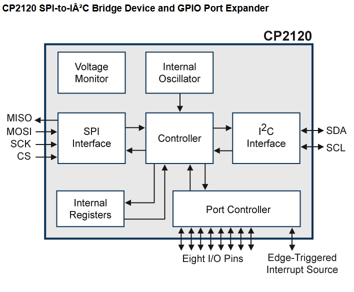
You could use an SPI to IIC bridge like this device.

enter image description here

\$\endgroup\$
4
  • \$\begingroup\$ Yeah; I'm aware of that but it's big and expensive. :) I'm sure I can do something myself much easier, as I don't need to bridge SPI to I2C, I just need to be able to talk both from the ATtiny \$\endgroup\$
    – LeoNerd
    Commented Jan 14, 2015 at 14:11
  • 1
    \$\begingroup\$ You never mentioned size and cost was an issue in your original question and what can be easier than a chip that's intended for the job? \$\endgroup\$
    – Andy aka
    Commented Jan 14, 2015 at 14:15
  • \$\begingroup\$ That's fine. Your answer is certainly valid for some use cases, and is likely useful to other readers of this question; it's just not suitable for me, so I'm seeking other answers additionally. \$\endgroup\$
    – LeoNerd
    Commented Jan 14, 2015 at 14:19
  • 2
    \$\begingroup\$ Maybe you should amend your question to require a solution needing to cost less than $2 and occupy less than 4mm x 4mm board area. \$\endgroup\$
    – Andy aka
    Commented Jan 14, 2015 at 14:23
2
\$\begingroup\$

The solution I settled on was to use a single-gate version of the 4066, namely a 74VHC1G66 (which is a tiny SOT-23-5 part) as a transmission gate to link the SDA part of the I²C bus onto the appropriate pin of the USI module.

The transmission gate's control input is active-high, which means I can control it from the slave-select line of the SPI chip. When the SS line is high, the gate is conducting and I²C will work through it (bidirectionally) while the SPI chip ignores it. When the SS line is low, the SPI chip is paying attention to the line now working in SPI mode, and the I²C chips don't see anything because the gate is in high-Z state, and the pull-up resistor on the SDA line keeps it high.

This is an easily-extensible arrangement if more than one SPI slave is added, because they can be diode-ORed together with a pullup resistor on the 1G66's control line.

\$\endgroup\$
1
\$\begingroup\$

You can mix a SPI and an I2C bus on the same four pins (with no additional hardware) if you only have one SPI device.

Pin 1 is SPI chip select and I2C clock.
Pin 2 is SPI MOSI and I2C data.
Pin 3 is SPI clock.
Pin 4 is SPI MISO.

In order to talk over I2C...

Keep pin 3 and 4 static, and then talk over I2C as normal.
The SPI device will see a chip select but no clock so nothing will happen.

In order to talk over SPI, just use the SPI bus as normal.

Note that unless you are trying to create an I2C start or stop condition you must take care to never toggle pin 2 while chip select is high.

While the chip select is low the I2C device will just see a clock stretch since the chip select is shared with the I2C clock. It will ignore all the data transitions on the data pin because it is only supposed to latch data on the rising edge of the clock, and even then only after having seen a valid start condition.

\$\endgroup\$
2
  • \$\begingroup\$ Yes; that's a valid option in some cases. But in my case, the SPI device is a radio module (the nRF24L01+), which I'd like to be talking nicely fast to. \$\endgroup\$
    – LeoNerd
    Commented Dec 12, 2016 at 16:34
  • \$\begingroup\$ @LeoNerd Nordic semi sells chips in the nRF series that have an integrated 8051 MCU. If you used one of those you could eliminate the need for a SPI interface altogether. \$\endgroup\$
    – user4574
    Commented Dec 12, 2016 at 21:07

Your Answer

By clicking “Post Your Answer”, you agree to our terms of service and acknowledge you have read our privacy policy.

Not the answer you're looking for? Browse other questions tagged or ask your own question.