5
\$\begingroup\$

I'm designing a class E resonant inverter at a switching frequency of approx. 2 MHz. I need to control the inverter so as to maintain a constant current at the load. My strategy would be to put a current sense resistor in series with the load to convert current to voltage, rectify and low-pass filter it, then read the essentially-DC value with an ADC -- I can take it from there.

Just to get a sense of the values involved, my nominal current is 0.17 A RMS, and I have determined that a 1 Ω current sense resistor is about the maximum value I can use. Hence the voltage drop on the current sense resistor is 170 mV RMS. I can tolerate at most 1% error on the amplitude of the sine wave at the output of my circuit. The circuit must work with a single power supply (say 3.3 V); no bipolar supplies.

Obviously this voltage is too low to rectify with a diode directly. My first thought was to use a precision rectifier; the following circuit, taken from a TI application note, might do the job, and it works for a single supply:
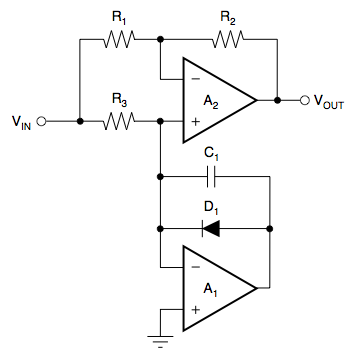
Precision rectifier circuit

Yet, certain performance demands are made of the op amps in this circuit, so as to meet my requirements above, that narrow down choices considerably:

  • The GBW product must be significantly higher than 4 MHz (twice the sine wave's 2 MHz frequency since this is a full wave rectifier); otherwise, the signal will be attenuated. I have determined that, if the 3 dB cutoff is one decade above the signal frequency, the amplitude will be attenuated by 0.5%, so a 40 MHz GBW amplifier is the bare minimum I'm looking for.

  • Since the amplitude of the sine wave is 240 mV, if I impose a maximum of 0.1% error due to the op amp's input offset voltage, I need a part with at a maximum of 240 µV offset.

  • Assuming a value of 10 kΩ for \$R_1\$ and \$R_3\$, the circuit should have an input impedance of 5 kΩ. Given the source impedance is 1 Ω, this by itself is not a problem, but op amp bias current is. Again imposing a maximum of 0.1% error due to the input bias current of the op amp, the maximum input bias current must be 240 µV/5 kΩ = 48 nA.

The cheapest (Digi-key qty. 1) op amp from a reputable manufacturer that meets these specs is the OPA2365 at $2.73. This would easily account for more than 10% and closer to 20% of the cost of my inverter, so I keep thinking there must be a better way. If it helps, this can be viewed as a peak detection or AM demodulation problem.

So the question is: can anyone suggest a cheaper circuit capable of measuring the amplitude of a ~240 mV, 2 MHz sine wave?

Edit: this circuit will be employed in a portable device, so power consumption must be kept in check.

Edit 2: As per @SpehroPefhany's answer, I'm trying to design a BJT circuit now. It goes something like this:
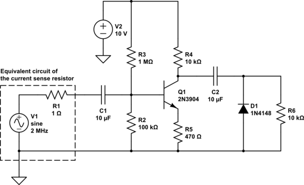
schematic

simulate this circuit – Schematic created using CircuitLab

Yes, I know I cheated there by using a 10 V supply -- I have batteries on my system that can provide this voltage if necessary, which is something I forgot to mention above. Also, I've omitted the filtering part of the circuit; that should be easy after rectification takes place correctly. I can add back the diode drop voltage digitally after A/D conversion of the signal, and since it's amplified (I'm shooting for say 4.5 V amplitude now), I can easily tolerate 50 to 100 mV variations on diode voltage drop in manufacturing without violating my revised accuracy target (5% now, again as per @SpehroPefhany's suggestion).

The problem with this circuit is that, with no load (assuming R6 were taken out of the circuit) the DC voltage on the diode's cathode drifts up until rectification no longer takes place. If R6 is sufficiently low, the rectification effect is maintained, but at the cost of unduly loading the circuit, with a corresponding effect on the DC level seen on the load resistor.

This seems to be the most promising avenue of investigation until now. I welcome any suggestions to improve it.

\$\endgroup\$
9
  • \$\begingroup\$ How good a proxy would the DC current draw of your circuit be? \$\endgroup\$ Commented Jan 24, 2015 at 4:08
  • \$\begingroup\$ @SpehroPefhany I would like to avoid going that route, as the load is a fluorescent lamp, which has a weird V-I characteristic and needs current limiting in order not to blow up. Plus, in the ignition phase, the power supply efficiency drops down immensely and I'm not sure if I'd be able to tell whether the lamp ignited or not. \$\endgroup\$
    – swineone
    Commented Jan 24, 2015 at 4:16
  • \$\begingroup\$ How many of these are you making? Could the control of your costs just be a matter of discounts from a bulk supplier? \$\endgroup\$ Commented Jan 24, 2015 at 4:59
  • \$\begingroup\$ Would a current transformer be any cheaper? I have never used one, don't know much about them. But it seems like just the thing, IF it is accurate enough. Which brings up another question. Are you going to mass produce? Would individual trimming be acceptable? If so, you can trim out some stuff and maybe relax some of your specifications. \$\endgroup\$
    – user57037
    Commented Jan 24, 2015 at 6:23
  • \$\begingroup\$ Sure buying in bulk would reduce the cost of the op amp, but so would the cost of everything else in the circuit. The ratio of op amp cost to total circuit cost would remain about the same. It just feels excessive to me to spend ~20% of the cost of a power supply just on signal conditioning for the control section. \$\endgroup\$
    – swineone
    Commented Jan 24, 2015 at 10:48

4 Answers 4

4
+100
\$\begingroup\$

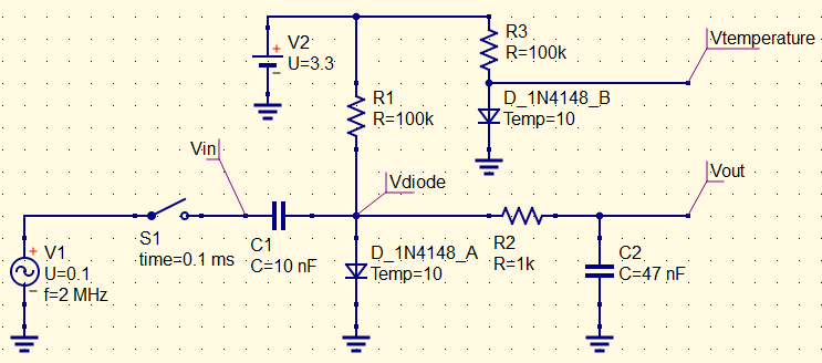
Here's an idea: A simple and rough solution by biasing a diode with a small current. It becomes non-linear and rectifies even quite small AC voltages.

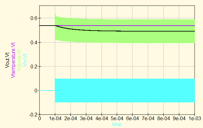
I've drawn a possible circuit. You could refine all of the values to suit your exact requirements. D_A and D_B are a pair in one SOT23 case. R1 and R3 supply the bias current to the diodes, from a 3.3 V rail. R2 and C2 are a filter to reject the 2 MHz and provide a stable output; they have a time constant well under 1 ms, very little 2 MHz gets through. A larger R2 or larger C2 might be a good idea, depending on the speed of your control loop. To use this circuit you must sample and process both the rectified RF output, and the temperature sensing output, and do some calculations on the results. (The switch is only to allow me to see the difference between RF On and RF Off). Circuit Diagram

Advantages of this circuit:

  • Cheap at under $0.10 for components (excluding the sense resistor)
  • No exotic components - Just one dual-1N4148 and some R and C.
  • Sensitive down to 50 mV AC, but errors will creep in
  • Very little part sensitivity, as long as the two diodes are matched and at the same temperature, or in the same package. Use 1% resistors.
  • Very little frequency sensitivity
  • Very little temperature sensitivity, once compensated (not sensitive to tempco of capacitors)
  • Low component count
  • Also acts as a thermometer

Disadvantages:

  • Is also a thermometer. You need to regularly sample the other diode, to check the junction voltage due to the temperature alone.
  • Some calculations to be done in software, could be as simple as a subtraction.
  • No voltage gain. Vout drops by about 270 mV with a 240 mV (RMS) AC input
  • Slightly non-linear response, DC voltage is not linear with AC voltage.

It works like this: Overall Voltages

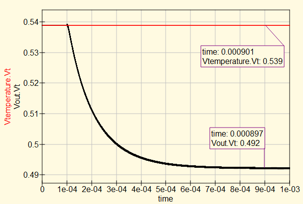
And plotting only the output DC voltages (here with a 100 mV peak AC signal): DC output voltages

BOM, (lowest cost reels from DigiKey)

  • 1 x pair of diodes: $ 0.01560
  • 3 x 100k resistors: $ 0.00093 each
  • 2 x Ceramic NP0 capacitors: $ 0.03914 each Total BOM: about $ 0.09667

A quick investigation into the sensitivity of the circuit to parameter variations shows that once the equations are worked out, it should not be sensitive to temperature, frequency or changes in capacitance.

Starting with 2 MHz, 10 deg C, and 100 mV AC (Peak):

  • Base configuration: 539 (Vtemp) to 492 mV (Vout), 47 mV difference
  • 40 deg C : 449 to 406 mV, 42 mV No sensitivity to temperature (after subtraction)
  • 1.5 MHz : 539 to 492 mV, 47 mV. No sensitivity to Frequency
  • R1/R3 22K: 599 to 553 mV, 46 mV. No sensitivity to current, works well with more bias current. Source impedance of rectifier now drops too, it now stabilises in 0.3 ms instead of 0.6. R1 and R3 must still be matched...
  • 50 mV AC: 539 to 525 mV, 14 mV (practical lower limit of voltage)
  • 200 mV AC: 539 to 409 mV, 130 mV
  • 339 mV AC: 539 to 284 mV, 255 mV (This is your operating point, 240 mV RMS)
  • 356 mV AC: 539 to 268 mV, 271 mV (operating point + 5%)

In Summary

  • This circuit rectifies a 240 mV RMS AC voltage, to provide a 250 mV change in DC voltage.
  • If the AC voltage changes by 5%, the DC voltage changes by about 6%, a delta of 16 mV.
  • It has no sensitivity to typical component tolerances, that would cause errors beyond 5%.
  • The exact DC value depends on temperature, but this is easily calibrated by comparison with a second diode in the same package, with the same bias but no AC.
  • A 12 bit A/D will give a resolution of about 0.25% per LSB, though in practice the resistor tolerance and diode matching will limit the accuracy long before this.
\$\endgroup\$
5
  • \$\begingroup\$ That's definitely an interesting idea. I'm just a little worried whether it's going to require calibration for each device assembled, due to variations from one diode to the next? \$\endgroup\$
    – swineone
    Commented Jan 28, 2015 at 0:37
  • \$\begingroup\$ @swineone It depends on a good model of Temperature and Voltage effects. The equation will be fun to work out, but it's free in production. Then component variations. It's not frequency sensitive, so I think the capacitor tolerance and tempco won't matter too much. 100k must be well matched. Will require matched diodes in one package, so the cheapest pair might not be good enough. Fairly easy to arrange though. \$\endgroup\$
    – tomnexus
    Commented Jan 28, 2015 at 5:20
  • \$\begingroup\$ I had a scheme to self-calibrate: add a 330 series resistor before C1, connect to a pin of the micro. Then you can keep it Hi-Z to measure current, hold it low to measure temp, and drive it at 2 MHz to calibrate voltage. But I didn't think it would add much accuracy, so went with the second diode for temperature instead. \$\endgroup\$
    – tomnexus
    Commented Jan 28, 2015 at 5:21
  • \$\begingroup\$ @swineone I've tried some further simulations for component variations, and it isn't really sensitive to anything except diode matching and bias current. I also see it produces a 270 mV DC change for your 240 mV RMS AC. I've edited above. \$\endgroup\$
    – tomnexus
    Commented Jan 28, 2015 at 20:55
  • \$\begingroup\$ You don't 'check the temperature', you take the differential output between the temeprature and Vout terminals. \$\endgroup\$
    – Neil_UK
    Commented Aug 19, 2017 at 6:35
3
\$\begingroup\$

Just about any discrete BJT can easily amplify 2MHz, or (given the very low source impedance) you could use a tapped inductor or transformer to increase the voltage to something more reasonable for a Schottky diode to handle. With emitter degeneration you could get fairly good gain accuracy with the BJT. I would expect something like a single turn primary and maybe 20 turn secondary for the transformer, through a small ferrite toroid.

I do think an unadjusted accuracy of 1% at 2MHz is possibly an unreasonably tight specification for a light and will result in very high costs. An accuracy of 5% or even 10% and stability of ~1% over some temperature etc. might make more sense.

\$\endgroup\$
3
  • \$\begingroup\$ After giving this some thought, I have to concur that 5% accuracy is a far more realistic specification. About the BJTs, I'd say biasing the BJT using a single supply would be problematic -- I'd need a resistive divider with resistances close to the value of the current sense resistor. Assuming a divider of two 1 Ω resistances and a 3.3 V supply, I'm looking at ~2 A of current through the resistors. I forgot to mention on the question, but this is a portable device, so this solution would be obviously unacceptable. \$\endgroup\$
    – swineone
    Commented Jan 25, 2015 at 13:13
  • \$\begingroup\$ Also, given this is a resonant converter, I'm not sure if adding a transformer is a good idea. It would shift certain critical parameters of the circuit, such as resonant frequency, loaded Q factor, load matching, etc. \$\endgroup\$
    – swineone
    Commented Jan 26, 2015 at 14:06
  • \$\begingroup\$ @swineone It should be designed not to affect the circuit any more than a sense resistor would. \$\endgroup\$ Commented Jan 26, 2015 at 14:45
0
\$\begingroup\$

As an alternative, since the current will be within a fairly narrow range, you might try something like

schematic

simulate this circuit – Schematic created using CircuitLab

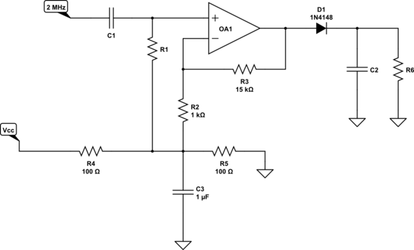
The idea is that, although 170 mV is too small to rectify, there's no reason you can't amplify it until it is big enough. R4, R5 and C3 make a virtual ground at 2.5 volts (for a 5-volt system), and C1 and R1 AC-couple the signal referenced to this virtual ground. OA1 is a fairly fast rail-to-rail op amp like an AD8655. The output is rectified into R6 and C2.

There are two possible problem areas. The input high-pass will introduce some phase shift, but I'd expect that at 2 MHz that shouldn't be a problem. The output low-pass filter is more problematic. I don't know your loop dynamics, so I can't tell if the response would be fast enough. Certainly you can trade off ripple for speed, but I really don't know if the end result would be satisfactory. Attack time is set by the dynamics of the diode/capacitor, and fall time by resistor/capacitor.

\$\endgroup\$
1
  • \$\begingroup\$ The idea is interesting, but the AD8655 is roughly as expensive as the OPA2365 I mentioned in my question, and I also believe current consumption will be a little excessive because of the R4/R5 resistive divider (I will update my question to make it clear that it's a portable device). \$\endgroup\$
    – swineone
    Commented Jan 26, 2015 at 19:26
0
\$\begingroup\$

Synchronous rectification using analogue switches might work. You have a 2MHz sine signal that can be converted to a square wave to drive the analogue switch. The analogue switch would open and close at the same rate and phase of the sine wave to be measured. This basically gives you a half wave rectifier and I believe half wave rectification is all you might need. An RC low pass filter converts this to a DC value. It can be converted to full wave.

You can possibly solve this problem with a sample and hold circuit - if you can get the timing right you can sample the peak of the signal you are wanting to measure and this directly gives you a DC signal. To get the timing right, differentiate the signal and use a zero cross detector to produce a pulse that activates the sample and hold.

\$\endgroup\$

Your Answer

By clicking “Post Your Answer”, you agree to our terms of service and acknowledge you have read our privacy policy.

Not the answer you're looking for? Browse other questions tagged or ask your own question.