0
\$\begingroup\$

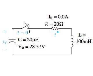
I was trying to solve the following second order linear circuit:

Second Order Linear Circuit

I managed to calculate all parameters but one: the Voltage of the Inductor at t=0, that is necessary to define the B parameter of the solution.

I tried to calculate it considering the closed network of the inductor, R2 and the capacitor.

The voltage of the capacitor should be 28.57 V. Considering the circuit a t=0, R2 has the same voltage (the capacitor at t=0 can be considered as an open-circuit, so they have the same voltage). So the Inductor Voltage should be (-, probably) 28.57 V (-) +28.57 V=(-)57.14 V. But, considering the inductance (0.1 H) the solution is:

Solution

Instead of 571.4 V.

So? Should i consider the circuit at 0+ instead of 0-? Or i forgot something?

\$\endgroup\$
5
  • 2
    \$\begingroup\$ You don't give any initial conditions for the inductor or capacitor, so I assume Il=0 and Vc=0? The capacitor is not an open circuit at t=0, more like a short. The inductor current at t=0 is 0, so the voltage across the inductor should be 28.57V at t=0. \$\endgroup\$
    – John D
    Commented Jan 30, 2015 at 16:35
  • \$\begingroup\$ At t=0, Il=0 but Vc=28.57V. If Vc(0)=28.57 it wouldn't break the KVL, considering the voltage of R2? \$\endgroup\$
    – EagleOne
    Commented Jan 30, 2015 at 16:38
  • \$\begingroup\$ If the given initial condition on the cap at t=0 is 28.57V, then the voltage across the inductor at t=0 is 0V. If the cap is discharged at t=0 then the voltage across the inductor is 28.57V. \$\endgroup\$
    – John D
    Commented Jan 30, 2015 at 17:01
  • \$\begingroup\$ What @JohnD said, I don't see how the initial charge on the cap can be ~28V. (It would just ring down through R2...) \$\endgroup\$ Commented Jan 30, 2015 at 19:19
  • \$\begingroup\$ Actually after putting my glasses on I see that the switch opens at t=0, I was thinking it closed at t=0. But similar principles apply. If the switch has been closed for a long time then we can say the voltage across the inductor is 0 and the voltage on the cap is 28.57. In steady state the inductor is a short and the cap is an open in this case. If the switch hasn't been closed for "a long time" then we need to know the initial conditions Il and Vc. \$\endgroup\$
    – John D
    Commented Jan 31, 2015 at 0:02

2 Answers 2

0
\$\begingroup\$

The moment you open the switch, voltage over R2 drops to zero, while the current through L was already 0 because of the charged capacitor, so the situation at t(o) is no different from the one below unless the circuit wasn't in steady state yet when the switch was still closed.

enter image description here

\$\endgroup\$
1
\$\begingroup\$

Energy storage in an inductor is in magnetic flux, which is related to the current through the inductor.

Therefore, the initial conditions for the circuit are given by the capacitor voltage and the inductor current. If you're only told "the switch has been closed for a long time", then you must determine the steady state of the part of the circuit with the switch closed. And realize that neither of the initial condition variables (\$I_L\$ and \$V_C\$) can change instantaneously --- their graphs will be continuous in time.

Once you know the two initial conditions at t=0, then you can use Kirchoff's laws to find the current through R1 and R2 after the switch opens, and these will give you the initial inductor voltage.

\$\endgroup\$

Your Answer

By clicking “Post Your Answer”, you agree to our terms of service and acknowledge you have read our privacy policy.

Not the answer you're looking for? Browse other questions tagged or ask your own question.