2
\$\begingroup\$

I am trying trying to control a 5V relay (SRD-05VDC-SL-C) with the ATtiny85. I have a simple sketch uploaded (Blink without Delay example):

const int ledPin =  0;      // the number of the LED pin
int ledState = LOW;             // ledState used to set the LED
unsigned long previousMillis = 0;        // will store last time LED was updated
const long interval = 1000;           // interval at which to blink (milliseconds)

void setup() {
  pinMode(ledPin, OUTPUT);      
}

void loop()
{
  unsigned long currentMillis = millis();

  if(currentMillis - previousMillis >= interval) {
    previousMillis = currentMillis;   

    if (ledState == LOW)
      ledState = HIGH;
    else
      ledState = LOW;

    digitalWrite(ledPin, ledState);
  }
}

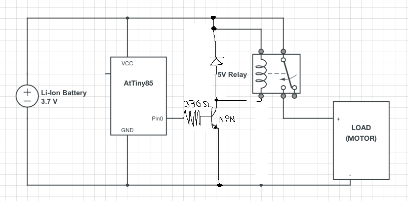
The whole thing is being powered by an 18650 Li-Ion battery (3.7V-4.2V) and the measured input is averaging 3.88V. Here is a quick sketch of how the circuit looks like: ATtiny85 motor control circuit using relay

Some issues comes up WITHOUT the motor connected:

  1. If I connect the battery and relay directly, you can hear it click, despite it being rated at 5V input.
  2. If I try to trigger the relay from Pin0, the oscilloscope will show the voltage of Pin0 to be about 2.72V, when the relay looks to be switching. If I replaced the relay with an LED, the voltage of Pin0 is about 3.88V. What causes the drop in voltage? I believe the current should be enough since it's an Li-Ion battery.
  3. What sort of protection do I need to implement in this circuit?
  4. Will the Li-Ion battery be enough to power this circuit? If I connect just battery, relay, and motor, it runs fine. The issue comes with the addition of the ATtiny85.
\$\endgroup\$

3 Answers 3

5
\$\begingroup\$

You should not really drive the relay coil directly from the microcontroller pin.

Instead, I would recommend using an NPN transistor between GND (emitter) and the coil (collector), then connect the other side of the coil to the positive supply directly.

Connect a diode backwards in parallel to the coil (i.e. diode cathode to positive supply, diode anode to transistor collector). This is a "fly-back" diode to protect against the back-EMF you get with the coil switches.

Put something like a 330 ohm resistor in series between the transistor base and the microcontroller pin. This limits the current into the base of the transistor to a level that is within the capabilities of the microcontroller.

That's the most common way I know of to control a relay with a GPIO pin of a micrcontroller.

enter image description here

\$\endgroup\$
3
  • \$\begingroup\$ Thanks. This works perfectly. But current from one 18650 seems to not be enough to start the motor perfectly 100% of the time. Most of the time it doesn't start because it's not enough. Do you know of any techniques to overcome this? \$\endgroup\$
    – PGT
    Commented Feb 16, 2015 at 21:38
  • \$\begingroup\$ Also, it seems now the whole thing doesn't work when I connect the motor. Oscilloscope is showing the relay not switching, it makes a click sound, so I guess it tries to switch but doesn't get all the way there or something resets. Increase voltage/current doesn't help either; I'm using a bench power supply now. \$\endgroup\$
    – PGT
    Commented Feb 16, 2015 at 21:46
  • \$\begingroup\$ you could try reducing the size if the base resistor to some extent, and be sure to use a transistor and coil voltage appropriate to your relay demands. \$\endgroup\$
    – vicatcu
    Commented Mar 11, 2020 at 12:34
0
\$\begingroup\$

Recommend adding some serial debug output to that sketch. Motors + micros without some type of supply isolation normal equals a microcontroller that is constantly reseting. Serial outputting the loop count might show it just keeps reseting.

You'll likely need a few capacitors to filter it. Maybe even an LC filter.

\$\endgroup\$
4
  • \$\begingroup\$ Can you recommend any tutorials on how to set up and use serial debug? Thanks \$\endgroup\$
    – PGT
    Commented Feb 16, 2015 at 0:03
  • \$\begingroup\$ Are you are using Arduino IDE and bootloader? \$\endgroup\$
    – James
    Commented Feb 16, 2015 at 0:06
  • \$\begingroup\$ Yes, a fake Uno, CH340G usb-to-serial chip is on it. I can use serial monitor fine in the arduino IDE. Not sure how to verify bootloader? Although I haven't done anything with it so I assume default bootloader still in there. \$\endgroup\$
    – PGT
    Commented Feb 16, 2015 at 0:08
  • \$\begingroup\$ Try Peter's answer 1st since it is most likely to solve your issue. Please reference the Arduino website for printing to COM. \$\endgroup\$
    – James
    Commented Feb 16, 2015 at 0:14
0
\$\begingroup\$

The output circuit of the processor is not a zero-resistance switch. It is a couple of MOSFETs that have a finite resistance when turned on, and the voltage differences you are seeing are due to the voltage drop across the MOSFET due to the current you are attempting to draw from the output pin. The datasheet for the ATTiny should give the maximum recommended output current, and the voltage drop at that current.

You should have the output pin drive a transistor or FET that, in turn, controls the relay. This should allow nearly the full Vcc to be available to drive the relay.

\$\endgroup\$
2
  • \$\begingroup\$ Would it be better to use something like a BD679, that can handle the motor's current, and just omit the relay? \$\endgroup\$
    – PGT
    Commented Feb 16, 2015 at 0:16
  • \$\begingroup\$ I don't know that transistor. If it is an NPN, make sure that it can supply the motor current without requiring more base current than the ATTiny can safely supply. If it is a FET, be sure that it will be fully turned on with the gate bias the ATTiny can supply. \$\endgroup\$ Commented Feb 16, 2015 at 0:44

Your Answer

By clicking “Post Your Answer”, you agree to our terms of service and acknowledge you have read our privacy policy.

Not the answer you're looking for? Browse other questions tagged or ask your own question.