0
\$\begingroup\$

I have chosen a power harvester to power a few things as part of a wireless system. This one is the one I have and it seems to be operational:

http://www.powercastco.com/PDF/P2110-datasheet.pdf http://www.powercastco.com/PDF/P2110-EVB.pdf

It provides the proper voltage set around 3V, and otherwise fits the RF frequencies required including the range of dbms .

However, I want to characterize the rfid system further than the nominal values given on the data sheet. i.e. get experimental values as well as relevant information relating to my use case.

I have standard laboratory tools such as a signal generator, oscilloscope, etc. I have already gotten charge/discharge time of a capacitor at a given frequency and dbm. Further, I want to measure the charge times with different loads.

For my prototype, I will use the evaluation board with capacitors on it. My issue lies in that the power harvester only outputs one DC voltage at the threshold of 1V at the capacitor. This means that as I discharge it, and my reading goes to 0V for the output, the capacitor still has energy stored at that 1V threshold, and my Vout reading remains 'useless' with a 0v. As such when Vout is 0V and thus not providing power or discharging the capacitor. I am using the Vout and GND pins as well as the capacitor pins for readings.

How can I characterize this threshold, and the discharge past the threshold? What other things should I measure about the power harvester? Perhaps I am missing some information to do with the capacitors.
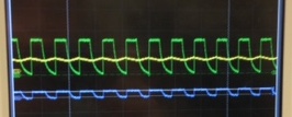
waves

\$\endgroup\$

1 Answer 1

1
\$\begingroup\$

I'm not sure I understand, but is there a problem to measure directly on Vcap (adding a resistor to load it there, or using the Dset pin and measuring the analog 'Dout' (less accurate resistor, but no boost converter, cap added to Dout))?

If you have the capacitor value Q=CV tells you how much charge is there. E=QV tells you the total energy in Joules. Q=C(Vcap-Vmin) gives a pretty close value for how much charge will be available at Vout if the boost converter is efficient, and E=C(Vcap-Vmin)*Vcap is the energy available for the boost converter.

Other than that, you can probably set the voltage at Vcap externally and measure how efficient the boost converter is.

And it seems a little bit silly here if the harvester cuts power practically at the same time as it tells you there is no power available anymore. Allthough that function might not be necessary in all applications though ...

\$\endgroup\$
4
  • \$\begingroup\$ I have added the waveforms generated and indeed measured Vcap(yellow), Dout(purple), and Vout(green) as before. The plateau on top is at ~3V then drops to 0V, as expected, for Vout. Delta V for Dout is only ~600mV, and Vcap as I mentioned oscillates around the 1V line. I am not sure how to interpret the latter two. The waveforms are to scale to each other. Could these waveforms give insight to the efficiency of the boost converter as you mention? Also, can you elaborate on the capacitance formulas you mention? with respect to voltage rating and capacitance of the capacitors in particular \$\endgroup\$
    – rednax
    Commented Mar 13, 2015 at 5:09
  • \$\begingroup\$ I believe that the datasheet said the device targets vcap for use with supercaps. Therefore the voltage swing is low on Vcap. It drops at a constant rate because the load on the boost converter is constant (P = V * V / R). You need to measure/know also the external loads. C (Vcap) and Rload. Then since Energy = Power * Time, you can look at energy input and output and compare. \$\endgroup\$
    – HKOB
    Commented Mar 13, 2015 at 6:11
  • \$\begingroup\$ That makes sense, so an arbitrary load R or something specific? The waves above were just with the impedances of the probes and nothing else... So if I understand you correctly, when adding the load to Vcap, I should not load Vout and just measure Vcap. Then derive energy from those readings and compare that to the dbm input in energy which I can find with a spectrum analyzer? \$\endgroup\$
    – rednax
    Commented Mar 13, 2015 at 14:19
  • \$\begingroup\$ Hi. Not exactly. Use a known resistive load on Vout. Use a known capacitor on Vcap. Make sure the probe is high impedance (ac coupling could work too. Measure Vcap. Discharge the capacitor if you want to look at charging from 0V. input energy should probably be forced/supplied as I imagine it will significantly affect results if you actually measure the input. \$\endgroup\$
    – HKOB
    Commented Mar 13, 2015 at 16:25

Your Answer

By clicking “Post Your Answer”, you agree to our terms of service and acknowledge you have read our privacy policy.

Not the answer you're looking for? Browse other questions tagged or ask your own question.