3
\$\begingroup\$

Is it possible to modify this flyback converter to get the output voltage somewhere up in the range of +/- 26-60v (preferably 30v or more) without having to make my own transformer? I would also like to use an input range of 6.5-9v. I saw another schematic that did +/- 15v output, but I can't find any standard examples going above that. This will only be driving a 50mA load max. I used the TI WEBENCH software to generate designs, but every thing I tried requires me to build custom inductors.
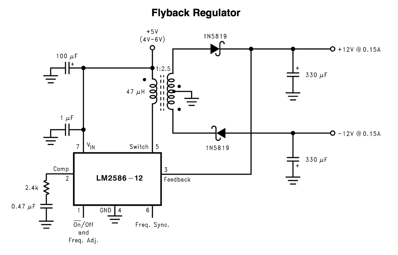
enter image description here

EDIT: I think I'm getting somewhere with the WEBENCH tool. I told it to generate a solution for a single 30v output and it told me to use this transformer:

http://www.digikey.com/product-detail/en/VPH4-0860-R/513-1542-ND/668203

Here is the schematic:
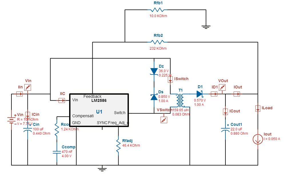
single output flyback

Then I went back and generated the dual output version that required a custom transformer for some weird reason:
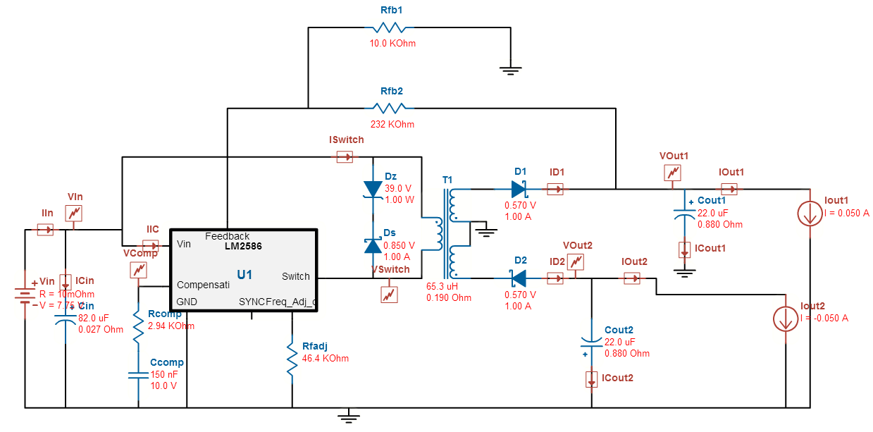
dual output flyback

Both transformer configurations are 1:3 so I think all I have to do is add D2 and Cout2 to the single output configuration and I should be good to go, right? The only other issue I can see is the different inductor value they suggested for the dual output version (65uH instead of 160uH). Is that significant or can I just use the 160uH?

\$\endgroup\$

1 Answer 1

4
\$\begingroup\$

An LM2586-12 is a 12V fly-back regulator chip - note pin 3 - it "sniffs" the dc output of the diode/capacitor and when it equals 12 volts the chip starts regulating the pulse width to maintain the output at 12 volts. If the 12V output rises a little high, the chip momentarily stops pushing energy thru the transformer.

Fly back designs are not like conventional transformers - in a fly-back design the circuit pumps energy into the transformer primary in one half cycle and that energy gets released by the secondary on the 2nd half cycle. The energy released produces a voltage that is load dependent and only in extreme cases of duty cycle requirements is the turns ratio altered to get a bigger/smaller output voltage. Typically, a 1:1 turns ratio produces input-output voltages that are the same value for a 50:50 duty cycle but this is load dependent too.

Try looking for an adjustable version of the LM2586 or maybe, as an experiment try potting down the feedback with a potential divider to "con" the chip that it is seeing 12 volts BUT before doing so, read the data sheet to see if they allow this.

\$\endgroup\$
3
  • \$\begingroup\$ Good point. If you take a look at the block diagram in the datasheet you'll see that the different fixed voltage versions just differ by two internal resistors around the feedback pin. Imho if you just drop the feedback voltage you'll get higher output. The chip won't even notice :-) \$\endgroup\$ Commented Mar 30, 2015 at 9:43
  • \$\begingroup\$ @andy I didn't notice that schematic was using the -12 version. There is a -ADJ version that I was planning on using (spent all day yesterday in the data sheet). So are you saying that the transformer doesn't matter that much and I can just adjust the feedback with resistors to get almost any voltage with +/- output? Also, see updated question. \$\endgroup\$ Commented Mar 30, 2015 at 17:34
  • \$\begingroup\$ @scubadude22 within reasonable limits the chip will adjust its duty cycle to accomodate larger voltages. I'm not saying definite just give it a try. \$\endgroup\$
    – Andy aka
    Commented Mar 30, 2015 at 19:13

Your Answer

By clicking “Post Your Answer”, you agree to our terms of service and acknowledge you have read our privacy policy.

Not the answer you're looking for? Browse other questions tagged or ask your own question.