0
\$\begingroup\$

So my two PV panels giving me an output of 40v, 1.5A. I am sensing both current and voltage of the PV output to give an MPPT duty cycle pulse. I want to boost the 40VDC to at least 400VDC and controlling the duty cycle of switching. I looked for multiple boost proposed circuits diagrams. some have transformers which I would not prefer to use in my design, I want the design to be a simple one but it has to do the job of stepping 40VDC to 400VDC. can you please provide me with the information or at least help me with the attached paper design

http://gistworldconpro.com/uploads/3/5/1420914303_313-_al_muzahid.pdf

Thank and regards, looking for your help please

\$\endgroup\$
1
  • \$\begingroup\$ What have you considered using so far? We aren't going to do your work for you - you have to show us that YOU have put some effort into YOUR problem. We will help you if we can but you have to put some effort in first. \$\endgroup\$ Commented Apr 13, 2015 at 3:45

1 Answer 1

2
\$\begingroup\$

The circuit that you provide seems not as straight forward as many you will find and has the disadvantages of both having a transformer AND being non-isolated.

What is your application?
Whay do youi need 400 VDC?
What will you do with the 400V?
You say "at least least 400" - is higher acceptable?

This may relate exactly to what you want
High Efficient Topologies for Next Generation Solar Inverter

As may this
Design Concept for a Transformerless Solar Inverter.

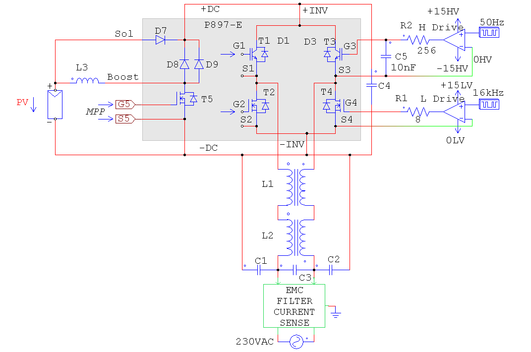
In the above page this circuit uses L3 and T5 to do the part that you are asking about.

enter image description here


Related:

More conceptual - but covers aspects you may need to know about
http://rtcmagazine.com/articles/view/103817

\$\endgroup\$

Your Answer

By clicking “Post Your Answer”, you agree to our terms of service and acknowledge you have read our privacy policy.

Not the answer you're looking for? Browse other questions tagged or ask your own question.