0
\$\begingroup\$

I have a loudspeaker for my car and I've added an aux cord to the system so that I can play music over it. There is also a microphone attached to it and what I've done is add a 3 way switch between the two so I can either use the microphone or the aux cable. I don't really like this setup and I want to be able to use both at the same time but I'm a software engineer, not electrical, so I'm not sure if tying the voltage of the aux and microphone to the same input is safe.

Here is a diagram with what I currently have:
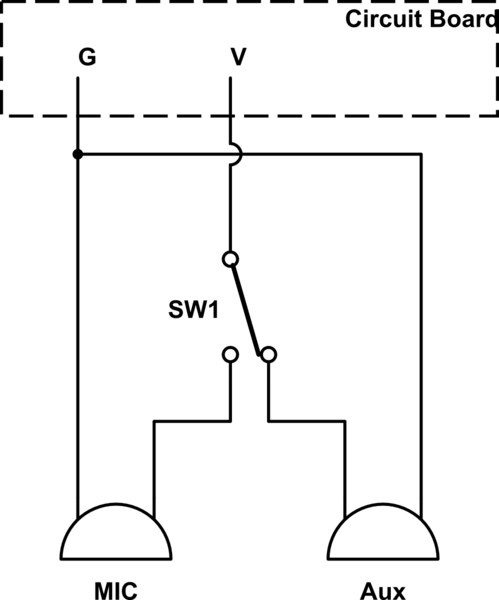
schematic

simulate this circuit – Schematic created using CircuitLab

And I want to remove the switch:
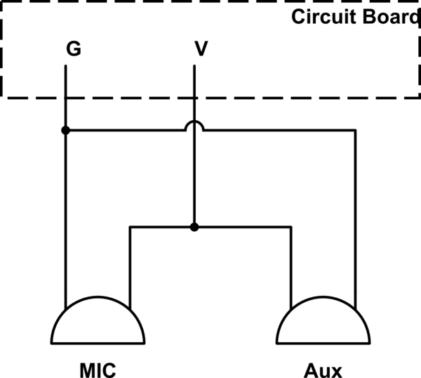
schematic

simulate this circuit

My roommate suggested adding diode to ensure the signal only goes one way but said that would lose about .7 volts. I don't like that as the input isn't that strong already and I have to manually amplify music in audacity so that you can hear it. While I'm asking a question, does anyone know how I would go about amplifying these signals through hardware because the microphone you really have to scream into and the aux is generally pretty soft compared to the tones/sirens it can generate. Unfortunately I don't have the schematics to the circuit board which is probably needed for something like that.

Here are some pictures of the circuit board/system: Circuit http://zyphox.com/misc/pa1.jpg

Front Panel http://zyphox.com/misc/pa2.jpg

\$\endgroup\$

2 Answers 2

0
\$\begingroup\$

In this case, there is only one microphone input configuration - the one that is hardwired to the unit. If you can measure the peak to peak voltage of the microphone, you can work out how different it is to the aux input (1VPP). Play a loud sine tone (low freq) into the microphone (as loud an input as is likely to be shouted into it), then measure it with the AC setting on a multimeter.

You might be able to use a simple potential divider to match the signal levels and then two series resistors to merge them together. Failing that, rebuffer them with an opamp.

Using series resistors will help to reduce one driving the other. If this were DC, diodes would work but as Techydude mentioned - music is AC, and using didoes will absolutely kill the signal.

Does the mic have a push-to-talk button on it? If not, and the mic is constantly picking up it might end up picking up feedback from the aux input.

EDIT: Measuring AC volts with a multimeter will give you RMS. You need to convert it to peak to peak to make a real comparison. Google "RMS to peak calculator".

\$\endgroup\$
1
  • \$\begingroup\$ Thanks for the information, this seems like what I want. \$\endgroup\$ Commented May 18, 2015 at 16:35
0
\$\begingroup\$

An 'aux' input is aka a 'line level input', around 1Vpp ac. A microphone input can be one of several configurations to support various types of mic. The two are not compatible. And you roommate knows enough to be dangerous - analog audio is an AC signal, goes +ve & -ve, so putting a diode in series will at best kill half of your audio & sound horrible, but as he said, it has a 0.7V forward voltage drop, which is enough to kill most of a 'aux' signal anyway - result will be silence or near-silence (& that's before getting anywhere near the amp's input impedance & whether the diode would actually turn on). In other words, buy him a beer and tell him to stick to what he does best :).

What you probably need is some 3rd-party 'line-level + microphone pre-amp switch' to achieve the combined functionality you're looking for.

\$\endgroup\$

Your Answer

By clicking “Post Your Answer”, you agree to our terms of service and acknowledge you have read our privacy policy.

Not the answer you're looking for? Browse other questions tagged or ask your own question.