0
\$\begingroup\$

I'm concerned about matching. If you look at the pictures, there is a certain tracewidth optimized for 50 ohm that is then changed to fit the pad of the rf component. How would I measure the amount of reflection in an already built system?

Situations: The RF board is already built, there is another component that generates the rf signal on the other side of the board, making the attachment of an sma connector to hook up a network analyzer not so likely. Even if it wasn't there, the trace is far from the board edge (maybe a right angle sma connector and unloading the rf generator?).

Additionally, it would be nice to test this for every board that comes through production (making attaching components not an option). Is there a way to test it with an rf probe (just a cable that you touch the tip of the cable to the trace) or some other method to ensure accurate matching?
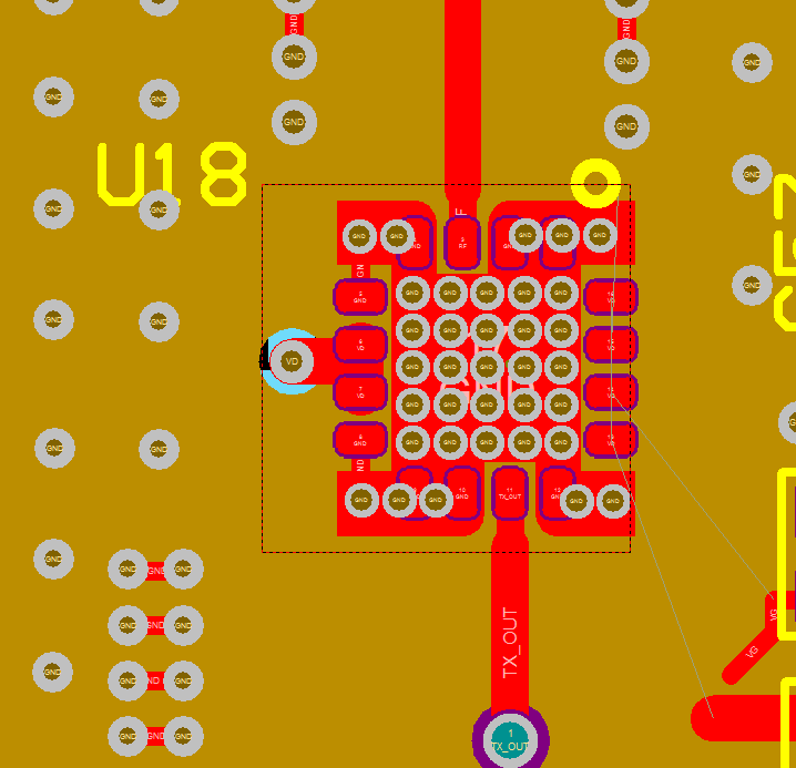
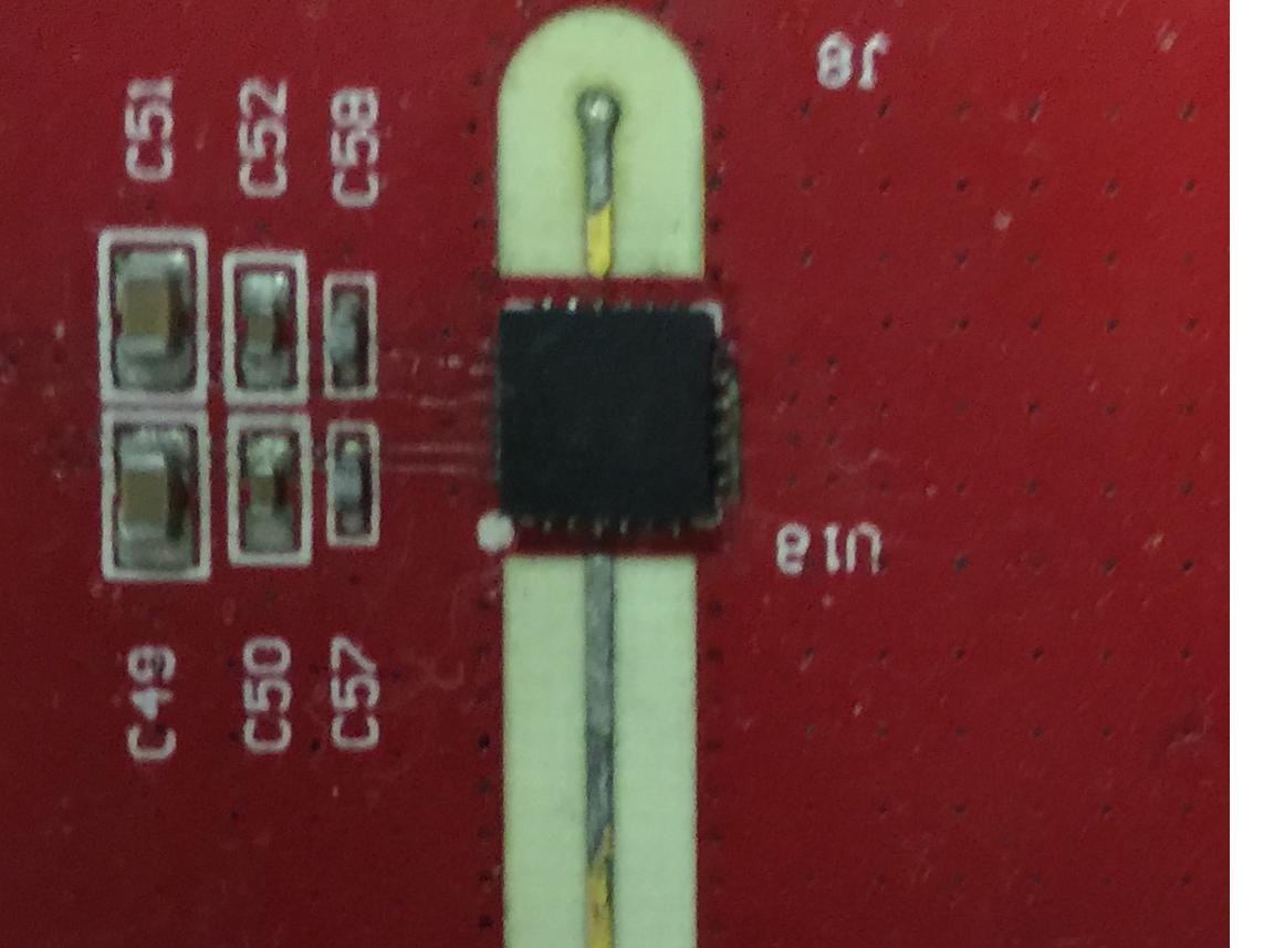
much bright very rf why is the real world so hard?

\$\endgroup\$
12
  • \$\begingroup\$ What's your operating frequency? \$\endgroup\$
    – The Photon
    Commented Jul 1, 2015 at 19:43
  • \$\begingroup\$ @ThePhoton above 2 ghz. \$\endgroup\$ Commented Jul 1, 2015 at 19:54
  • \$\begingroup\$ With a TDR or VNA? \$\endgroup\$ Commented Jul 1, 2015 at 20:00
  • \$\begingroup\$ 1 million tera hertz is above 2GHz. BTW that's capital G, capital H and not "ghz". If you are worried about a small section of trace nipping in a bit then how worried are you about the trace not appearing to be terminated in a matched load. \$\endgroup\$
    – Andy aka
    Commented Jul 1, 2015 at 20:21
  • \$\begingroup\$ @Andyaka I was going to make a point about that via. I assume you mean that one? \$\endgroup\$
    – Asmyldof
    Commented Jul 1, 2015 at 21:08

1 Answer 1

3
\$\begingroup\$

Some things to consider.

  1. The wavelength at 2 GHz is about 150 mm in vacuum, maybe 75 mm in FR4. Your discontinuity is much much shorter than that so isn't likely to have much effect on the signal.

  2. At 2 GHz, measuring with the chip in place, no matter what technique you use, you're not going to be able to tell the difference between a reflection caused by your PCB layout and a reflection caused by the chip termination and package.

  3. The track narrowing is producing an inductive parasitic. The nearby top-layer ground is producing a capacitive parastic. You shouldn't just be worried about the track narrowing. If you're lucky (or design for it to begin with) the two effects might balance each other out.

  4. If you still want to make a measurement, you have a few options:

    A. Active oscilloscope probes are nowadays available up to your frequency and beyond. Assuming you can make your system generate a single-frequency excitation, you could place the probe at different points along the line and estimate the VSWR.

    B. If you can't spend money on a GHz active probe, a 500-ohm resitive probe should be able to measure signals on your trace adequately. These have been available for many years. They do produce a small discontinuity on the line, and produce 10:1 attenuation of the signal delivered to the 'scope, so they're not necessarily ideal.

    C. Companies like Cascade make coplanar microprobes that might be able to contact your trace and the surrounding ground planes. If you do this with the source and load chips in place, it will produce a substantial discontinuity (essentially an un-matched tee). If you connect the microprobe in place of the source IC you should be able to do a nice TDR and see the discontinuities in your whole setup (traces, via, and termination).

\$\endgroup\$
3
  • \$\begingroup\$ add in the higher frequency ideas and I'll accept the answer. If you can measure it at 25 Ghz and add in tuning dots, you should be able to minimize the VSWR for both the trace and the component. \$\endgroup\$ Commented Jul 7, 2015 at 17:32
  • \$\begingroup\$ @LegenDiary, what I said before was: " at 25 GHz I would tell you you need to make a test coupon with appropriate connector footprints. At 2 GHz I think I have a few suggestions which I will write up when I have a bit more time." My suggestions for testing at 2 GHz are already included in my answer. \$\endgroup\$
    – The Photon
    Commented Jul 7, 2015 at 17:58
  • \$\begingroup\$ Test coupons is what I was referring to. It's in enough places now so someone should be able to find it \$\endgroup\$ Commented Jul 7, 2015 at 19:00

Your Answer

By clicking “Post Your Answer”, you agree to our terms of service and acknowledge you have read our privacy policy.

Not the answer you're looking for? Browse other questions tagged or ask your own question.