2
\$\begingroup\$

I have the Arduino Uno and the Adafruit Motor Shield, and they are powered by separate power supplies.

  1. I want my toggle switch to turn on and off those two, I would appreciate if someone post a picture with the hardware connection and whatsoever, followed by a brief explanation.
  2. What kind of batteries should I use to power the Arduino and to power the motor Shield?

  3. When I was powering both with the same battery, my ultrasonic distance sensor wasn't getting correct results when the motor was enabled, why is that?

(Probably it's obvious that I'm not an expert on the subject, I'm actually just starting to learn this kind of stuff, so I would appreciate if you guys could keep it simple).


This is a picture of what I'm trying to do:
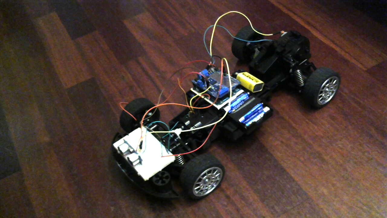
My project picture

\$\endgroup\$
1
  • \$\begingroup\$ You've really got several different questions here; if you split them into separate questions here on SE, you're more likely to get answers, and they're more likely to be useful to other people in future. \$\endgroup\$ Commented Jul 22, 2015 at 9:05

2 Answers 2

2
\$\begingroup\$
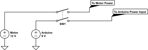
  1. You need either a double pole double throw or a double pole single throw switch if you would like to have both be controlled from the single switch. It is important the switch is on the positive voltage rail and that you are NOT using a single pole single throw on the ground of the power supplies. If you cut the ground to the power supplies you are actually creating a scenario where current will flow backwards through your micro and possibly damaging the arduino.

schematic

simulate this circuit – Schematic created using CircuitLab

  1. The arduino can be powered from anything over ~7V, so a 9V batter would be just fine. For the motor however you CAN NOT use a 9V battery and need a battery that is capable of supplying high current without the internal resistance of the battery hindering your output voltage. I highly recommend looking into either a LiPo or NiMh battery for driving the motor. The size of battery will be dependent on what the motor is rated for. For example if you have a 12V motor, you will want a 12V battery for them.

  2. This depends on the battery you are using, and can most likely always be traced back to the battery. In your picture you show a 9V radio battery being used, which is in fact a very poor choice for any sort of motorized circuitry - it simply isn't able to supply the needed current. When you ask a battery like a 9V for more current than it can supply it begins to compensate by reducing the output voltage (ok there is actually a lot going on internally chemistry wise but that is a valid way of thinking about it). This fluctuation in output voltage will effect high sensitivity devices such as analog circuits or high speed digital circuits (which the ultrasonic sensor is). Switching over to a battery that can supply high amounts of current would fix this, or switching to a two battery solution.

\$\endgroup\$
1
\$\begingroup\$
  1. You need a double pole, single throw switch. A little googling will give you the internal circuit of the switch.

2 and 3 are too broad in the current form.

  1. Possibly your motors were drawing too much power or injecting too much noise into the DC rail for the ultrasonic sensors to work. Again, difficult to deduce in the absence of any debugging info.
\$\endgroup\$
7
  • \$\begingroup\$ Sorry by the lack of information, anyway your answer was useful. My sensor is working correctly, and i'll follow your advice and try to google something about the switch. Thank you. \$\endgroup\$
    – 0gener
    Commented Jul 22, 2015 at 10:06
  • \$\begingroup\$ You could use an SPST switch, switching ground instead of the supplies. \$\endgroup\$ Commented Jul 22, 2015 at 10:25
  • \$\begingroup\$ @Nick - you might want to draw a circuit to illustrate that option in an answer... \$\endgroup\$
    – user16324
    Commented Jul 22, 2015 at 10:37
  • \$\begingroup\$ I agree with @Brian. \$\endgroup\$
    – 0gener
    Commented Jul 22, 2015 at 10:48
  • 1
    \$\begingroup\$ @kabZX With ground disconnected from all the batteries, there's no circuit, so no current can flow through any of the circuits concerned. If there's a path from the +12V source to the logic rail, that would flow even when the circuit's connected. \$\endgroup\$ Commented Jul 22, 2015 at 12:17

Your Answer

By clicking “Post Your Answer”, you agree to our terms of service and acknowledge you have read our privacy policy.

Not the answer you're looking for? Browse other questions tagged or ask your own question.