I have a small problem and hoping someone can help:
I am trying to design and build a reasonably universal underwater housing for some different cameras. there is a breakout box on the surface and the housing is cabled to this box for things like a video feed, ethernet control of the camera etc.
My current problem is power. As well as onboard batteries, I also want to feed power to the camera from larger DC block batteries located on the surface. There are two inputs on the breakout box, one accepts 12 V DC power + and - from a block battery and one accepts 24 V DC power + and - from different type of block battery. Inside the camera housing underwater, there are two power connectors (one 12 V with + and - terminals and one 24 V with + and - terminals) as I would like to support the use of both 12 V and a 24 V camera. These power connectors are different styles to avoid connecting a 12 V camera to a 24 V supply!
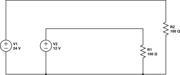
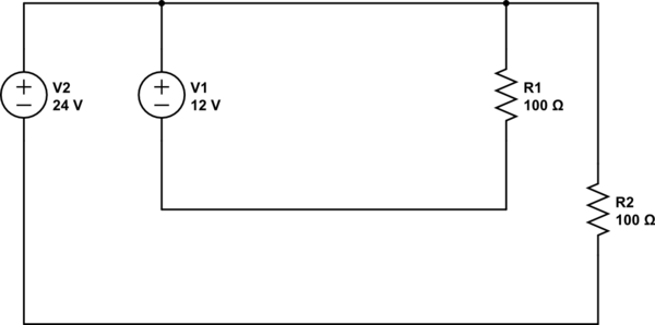
I only have three wires left on my underwater cable to carry power so can't just hard wire the 12 V input to the 12 V output and the same with the 24 V input/outputs as this would require four cables (this is an assumption on my part: You can't have 24 V positive going down cable 1 with 12 V positive down cable 2 and have them share the same negative cable 3. Please correct me if I'm wrong!).
I will only need one of these sources depending on whether a 12 V or 24 V camera is being used.
To solve this problem and make it the least amount of work for the user possible, I have the following solution:
inside the surface breakout box have a circuit that detects which power input has a battery plugged into it. If it's the 12 V battery, use cable 1 to the housing as positive and cable 3 as negative. If it's the 24 V volt battery, use cable 2 as positive and cable 3 as negative. If the user has plugged both a 24 V and 12 V battery, it should favour the 24 V and use the logic above but isolate the 12 V battery to prevent it overloading.
Down at the housing end, another circuit can detect whether positive current is coming down cable 1 (this would be the 12 V battery according to the logic above) or cable 2 (the 24 V). Based on this detection, it would the connect the power to either the 24 V or the 12 V outputs to power the camera.
I don't want to get into voltage measurement as 24 V and 12 V are expressed as simplifications. Actual voltages could vary (but would remain within camera tolerances). Also I wouldn't want to smooth voltage to a consistent level as the video feed from the camera includes an overlay that expresses voltage of the input power source that people use as a gauge of when to change the battery.
My questions are:
a) is this possible?
b) is there a better solution to my problem?
c) is it possible to just have voltage convertors at the camera housing end? (e.g. one that would take 10-30 V and convert to 12 V and one that would take 10-30 V and convert to 24 V). Overheating is a consideration for a camera in an enclosed environment but if this were a potential solution, I would accept voltage smoothing, contrary to what I mentioned above.


