2
\$\begingroup\$

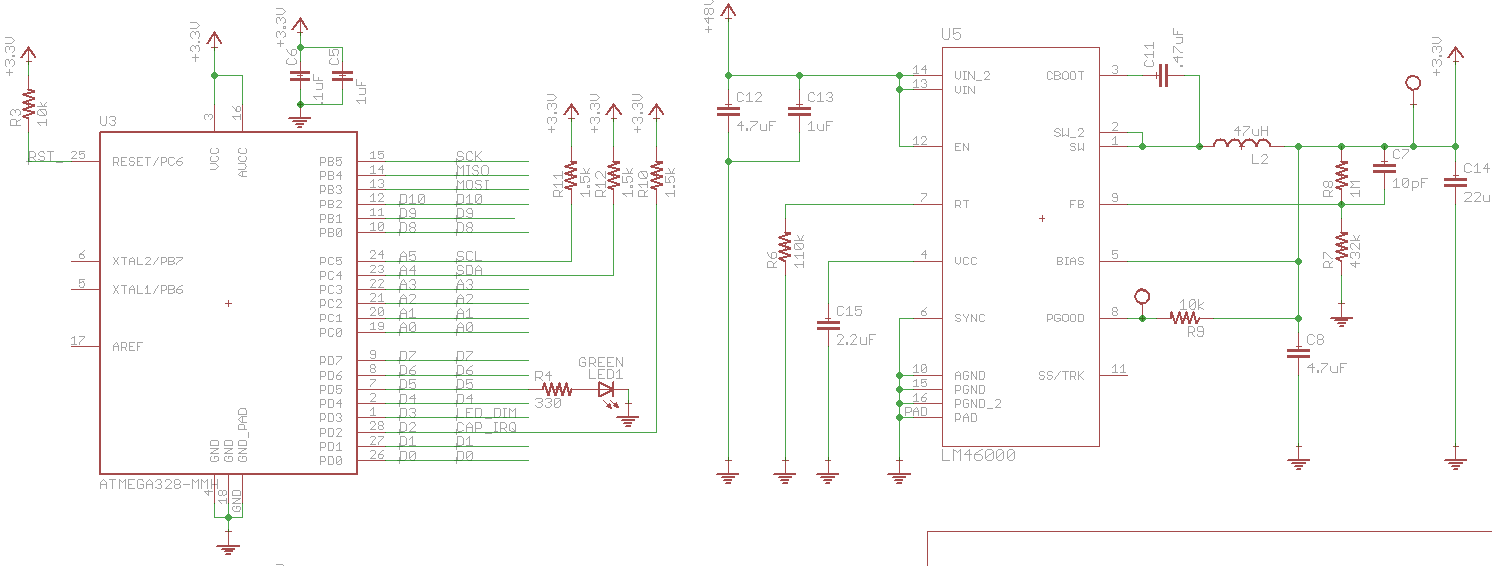
I have an AC powered microcontroller board. I use a CUI module (VSK-S15-48U) to generate 48V DC from the wall. That 48V gets bucked down to 3.3V to power a micro (atmega328-mmh) and some other peripherals (the 48V is used for other stuff). My power connection is pretty ugly -- I took a two prong extension cord/cut the female end off and crimped a connector, which mates to my board (read the connection is probably ugly and I'm definitely getting some transients when I plug in). The power supplies (48V and 3.3V) looks really nice/clean and there are no oscillations.

For simplicity/prototyping I'm using the arduino IDE. I've modified the avrdude.conf file such that I'm utilizing the internal RC oscillator at 8 MHz. I'm able to program the board without issue. I am, however, noticing that when I initially plug the board into the wall the microcontroller appears to be bricked: a test LED doesn't blink/turn on, another I/O I use appears to be pulled high somewhere, and my I2C lines appear to be tristated (they're pulled high so I read a high voltage). I tried manually resetting the micro using a push-button, but it seems as though it has zero effect. Initially it appeared as though it would "randomly" start working and the FW would be executed as expected. After that, reprogramming/resetting the micro worked as expected until I'd unplug and replug from the wall. Eventually I noticed that if I touched/tapped the area near the feedback resistor on the buck regulator that the micro would come out of its suspended/bricked state and function appropriately.

Initially I suspected a cold solder joint -- by tapping on the cap I electrically connected it. Resoldering didn't do the trick.

Looking with a scope, the 3.3V looks good after plugging the device into the wall -- I see nothing to suspect there's anything wrong with it. The power good output of the buck regulator indicates that the 3.3V is fine. When I tap on the bypass cap I can see the 3.3V wiggle down to ~2.2V for ~40 mS. The power good output drops accordingly and then sometimes the micro wakes up and decides to execute the code (occasionally a few taps are required).

I thought maybe the slope rate of vcc was somehow causing the micro to go haywire. The 48V rises in 10 mS and the 3.3 in roughly 2.5 mS. The datasheet requires between .01 and 10 V/mS so I'm in the clear there.

I still have some more debugging to do, but at this point I'm unable to find a logical explanation for why the micro doesn't come on initially and why tapping the feedback cap (and therefore causing the buck output to sag for a bit) kicks the micro into gear.

Edit:

I thought it might be beneficial to start the micro in reset by holding the button down and releasing after plugin -- makes no difference.

Schematic of the micro/buck:

enter image description here

\$\endgroup\$
3
  • \$\begingroup\$ What kind of transients are you getting when plugging the board in? Sounds like something similar to a latch-up. If tapping your board brings down the supply voltage by that much, there's likely another problem too though. \$\endgroup\$
    – svens
    Commented Aug 5, 2015 at 1:31
  • \$\begingroup\$ Almost none on the rails. Measured in couple of millivolts range on the 3.3 rail. I haven't carefully looked at the 48V, but in general that too looks good. The buck is meant to supply very little current. I suppose that if my body is somehow messing with the feedback network then the buck could respond accordingly. \$\endgroup\$
    – Doov
    Commented Aug 5, 2015 at 4:16
  • \$\begingroup\$ Try add a load resistor to the 3V3 supply output. Make it so it should consume about half of the excess current capacity after all your desired loads. So if you have a 150mA supply, need 20mA for your stuff put 65mA load about 50Ohm half Watt. This should get the switcher to regulate properly if your load is too light. \$\endgroup\$
    – KalleMP
    Commented Sep 7, 2015 at 11:38

2 Answers 2

1
\$\begingroup\$

Before you do a lot of debugging test all the other soldering places as well. I think maybe somewhere else it could have connection problems.

Maybe put an additional cap of about 100nF after your buck. It's better to have also one with a small esr. Touching the cap shouldn't reduce the voltage to 2.2V, I guess this could be a problem.

When you haven't found anything in the hw then there's maybe a hold state for power on. Have you unplugged your debugger and programmed the chip? Maybe he is keeping the chip in reset state until your voltage drop.

\$\endgroup\$
0
\$\begingroup\$

Always use power-on reset circuit if you dealing with not-so-good power source. A simple PNP transistor will suffice (in your case 0.75/3.3 resistive divisor, base to the middle point, emitter to +3.3, collector to GND through 1-10k resistor, MCU reset to the collector).

Useful PDF: http://www.st.com/web/en/resource/technical/document/application_note/CD00003839.pdf

\$\endgroup\$
8
  • \$\begingroup\$ I don't disagree with what you're saying, but I don't think it's relevant here. As mentioned the rails looks super clean and the micro has a built in POR. Perhaps you can elaborate? \$\endgroup\$
    – Doov
    Commented Aug 5, 2015 at 4:09
  • \$\begingroup\$ Built in PORs can be inadequate, potentially. \$\endgroup\$
    – ilkhd
    Commented Aug 5, 2015 at 4:19
  • \$\begingroup\$ @Doov I looked at your schematics and I would still suggest to add at least a 0.1 uf cap from RESET to GND and see if it helps. \$\endgroup\$
    – ilkhd
    Commented Aug 5, 2015 at 4:32
  • \$\begingroup\$ @Doov The cap will provide a small delay, enough for the PSU to fully settle down. \$\endgroup\$
    – ilkhd
    Commented Aug 5, 2015 at 4:35
  • \$\begingroup\$ I agree in principle that a cap won't hurt, but that is just not related to the issue I'm observing on board. The 3.3V rail has very little noise and rises to its nominal value within 2.5 mS. In other words it does not appear that the PSU needs any time to "settle down." Additionally if you look at the schematic for the arduino uno they also just tie reset high with a pullup. Not saying it's great design practice, but they've shipped hundreds of thousands (millions?) of boards with this micro and reset configuration. \$\endgroup\$
    – Doov
    Commented Aug 5, 2015 at 21:55

Your Answer

By clicking “Post Your Answer”, you agree to our terms of service and acknowledge you have read our privacy policy.

Not the answer you're looking for? Browse other questions tagged or ask your own question.